audi Workshop Repair Guides

Audi Workshop Service and Repair Manuals

Checking misfiring detection function > < Function of camshaft timing control
Motronic injection and ignition system (4-cyl.)
Checking camshaft timing control
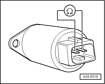
Checking camshaft adjustment solenoid valve -N205
  • ‒ Switch on ignition.
  • ‒ Perform final control diagnosis and actuate camshaft timing control .
 
→ Indicated on display:
Final control diagnosis    ⇒
Camshaft timing control 1

Solenoid valve must be heard to click distinctly on actuation of camshaft timing control.

 
A28-0019

Perform the following checks if reading does not match specification.

Electrical check on camshaft adjustment solenoid valve

  • ‒ Unplug connector from camshaft adjustment solenoid valve.
  • ‒ → Measure resistance with portable multimeter V.A.G 1526 between solenoid valve contacts.
  • Specification: 10 ... 18 ω

If reading does not match specification:

  • ‒ Replace camshaft adjustment solenoid valve.
 
V96-0749

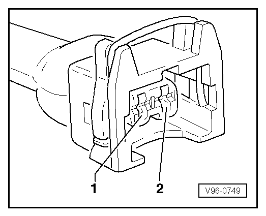
Checking power supply for camshaft adjustment solenoid valve

  • ‒ Unplug connector at solenoid valve.
  • ‒ → Connect diode test lamp V.A.G 1527 with leads from adapter set V.A.G. 1594 to socket 1 of connector (positive) and engine earth.
  • ‒ Operate starter for several seconds. Engine may also start.

Diode test lamp must light.

 
V96-0749

Perform the following checks if diode test lamp does not light.

  • ‒ Check fuse for camshaft adjustment solenoid valve.

=> Current Flow Diagrams, Electrical Fault-finding and Fitting Locations binder

If fuse is OK:

  • ‒ → Check for continuity in wiring from socket 1 of connector for camshaft adjustment solenoid valve via fuse to fuel pump relay.

=> Current Flow Diagrams, Electrical Fault-finding and Fitting Locations binder

 
V96-0749

Checking actuation of camshaft adjustment valve

  • ‒ Unplug connector at solenoid valve.
  • ‒ → Connect diode test lamp V.A.G 1527 with leads from adapter set V.A.G 1594 to sockets 1 (positive) and 2 of connector at solenoid valve.
  • ‒ Perform final control diagnosis and actuate camshaft timing control => Page 01-46.

 
→ Indicated on display:
Final control diagnosis    ⇒
Camshaft timing control 1

Diode test lamp must flash during actuation of camshaft timing control.

If diode test lamp does not flash or if it is permanently lit:

  • ‒ Connect test box V.A.G 1598/31 to engine control unit wiring harness. Actual engine control unit is not to be connected.

If diode test lamp is permanently lit:

 
V96-0749
  • ‒ → Check for short to earth in wiring from socket 2 of connector for camshaft adjustment solenoid valve.

If diode test lamp does not flash:

  • ‒ → Check for continuity and short to positive in wiring from socket 2 of connector for camshaft adjustment solenoid valve to socket 115 of test box.
  • Resistance: max. 1.5 ohms

=> Current Flow Diagrams, Electrical Fault-finding and Fitting Locations binder

  • ‒ If necessary, eliminate short circuit/open circuit in wiring.

If there is neither an open circuit in the wiring nor a short circuit, replace engine control unit => Page 24-16.

  • ‒ If no faults were found in any of the preceding checks, replace mechanical camshaft adjuster.

=> 4-cyl. Engine, Mechanics; Repair Group 15; Cylinder Head, Valve Gear; Removing and installing camshafts and camshaft adjuster

Checking misfiring detection function > < Function of camshaft timing control