audi Workshop Repair Guides

Audi Workshop Service and Repair Manuals

Checking Hall sender -G40 > < Checking knock control stop
Motronic injection and ignition system (4-cyl.)
Checking ignition system
Checking knock sensors 1 and 2 -G61 and -G66

Notes:

  • ◆ The actual knock sensors 1 and 2 -G61 and -G66 cannot be electrically checked (interrogate fault memory ).
  • ◆ Exact compliance with tightening torque of 20 Nm is essential to proper knock sensor operation.
  • ◆ Check connector for corrosion.
  • ◆ Exclusive use is to be made of gold-plated contacts when repairing contacts in knock sensor connector.
  • ◆ Check connector between knock sensor and wiring harness for corrosion.

Checking knock sensors

Fitting location of connectors => Page 24-5

  • ‒ Unplug connector of appropriate knock sensor in engine compartment.
 
A24-0089
  • ‒ → Check all three contacts at knock sensor connector for mutual short circuit (contacts 1+2, 1+3, 2+3).
  • Specification: No mutual contact between wires (infinity ohms)
  • ‒ Replace knock sensor if there is contact.
  • ‒ Check knock sensor wiring if no short circuit is found.

Checking wiring between knock sensors and engine control unit

 
A24-0096
  • ‒ Connect test box V.A.G 1598/31 to engine control unit wiring harness. Actual engine control unit is not to be connected.
  • ‒ → Check wiring between respective sensor connector ...
  • ‒ ... to engine control unit for open circuit and short to positive/earth.

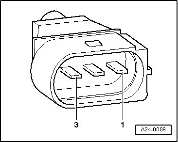
Knock sensor 1 -G61 (cylinders 1 and 2)

3-pin connector at wiring harness, socket

Test box V.A.G 1598/31, socket

1 (signal)

106

2 (earth)

99

3 (screen)

108

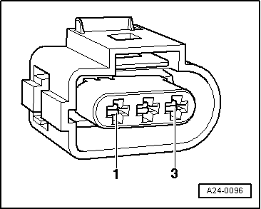
Knock sensor 2 -G66 (cylinders 3 and 4)

3-pin connector at wiring harness, socket

Test box V.A.G 1598/31, socket

1 (signal)

107

2 (earth)

99

3 (screen)

108

  • Resistance: max. 1.5 ohms

=> Current Flow Diagrams, Electrical Fault-finding and Fitting Locations binder

  • ‒ If necessary, eliminate open circuit in wiring/short circuit.

Checking Hall sender -G40 > < Checking knock control stop