audi Workshop Repair Guides

Audi Workshop Service and Repair Manuals

Testing knock sensors > < Testing coolant temperature sender
Motronic Injection and Ignition System (4-cyl.)
Testing ignition system
Checking control unit voltage supply

Note:

For testing the power supply to the engine control unit, see also "Reading measured value block", Display Group 03, display zone 2.

Test requirements:

  • ● Fuse for engine control unit OK
  • ● Battery voltage at least 11 V
  • ● Alternator OK
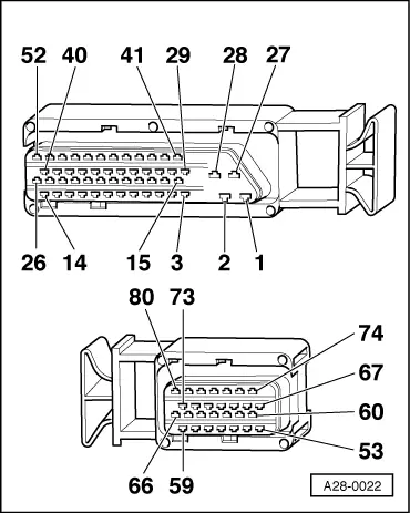
  • ‒ Connect test box V.A.G 1598/22 to wiring harness for engine control unit.
  • ‒ Switch ignition on.
  • ‒ Connect diode test lamp V.A.G 1527 to socket 1 (live positive supply via ignition switch) and earth.

The diode test lamp should light up.

 
A28-0022
  • ‒ → If the diode test lamp does not light up, test for open circuits using the current flow diagram and rectify if necessary.

=> Current flow diagrams, Electrical fault finding and Fitting locations binder

  • ‒ If diode test lamp V.A.G 1527 lights up, connect diode test lamp to socket 1 (live positive supply via ignition switch) and socket 2 (earth connection).
  • The diode test lamp should light up.
  • ‒ → If the diode test lamp does not light up, test wiring for open circuits using current flow diagram and rectify if necessary.

=> Current flow diagrams, Electrical fault finding and Fitting locations binder

  • ‒ Connect diode test lamp V.A.G 1527 to socket 3 (permanent live) and earth.
  • The diode test lamp should light up.
 
A28-0022
  • ‒ → If the diode test lamp does not light up, test wiring between central electrics and contact 3 on control unit connector using current flow diagram. Rectify any open circuits if necessary.

=> Current flow diagrams, Electrical fault finding and Fitting locations binder

Testing knock sensors > < Testing coolant temperature sender