audi Workshop Repair Guides

Audi Workshop Service and Repair Manuals

Learning kickdown function > < Significance of EPC warning lamp (electric throttle control fault lamp -K132)
Motronic injection and ignition system (4-cyl.)
Checking accelerator pedal position sender -G79 and -G185

The two senders -G79 and -G185 are located at the accelerator pedal and each sender relays the driver input separately to the engine control unit. Both senders are accommodated in a joint housing.

  • ‒ Connect vehicle diagnostic, testing and information system VAS 5051 or fault reader V.A.G 1551 and select engine electronics control unit with "address word" 01 .
    Ignition must be on.
 
→ Indicated on display:
Rapid data transfer    HELP
Select function XX
  • ‒ Press keys 0 and 8 for "Read measured value block" function and confirm entry with Q key.
 
→ Indicated on display:
Read measured value block    Q
Enter display group number    XXX
  • ‒ Press keys 0, 6 and 2 for "Display group number 62" and confirm entry with Q key.
 
→ Indicated on display:
Read measured value block 62    ⇒
    1    2    3    4
  • ‒ Check specifications for electronic throttle system potentiometer voltages.

Display zones

1

2

3

4

Display group 62: Electronic throttle system potentiometer voltages with ignition on

Display

xx %

xx %

xx %

xx %

Readout

Throttle valve angle
(angle sender 1)

Throttle valve angle
(angle sender 2)

Accelerator pedal position
sender

Accelerator pedal position
sender 2

Operating range

min.: 0 %
max.: 100 %

min.: 0 %
max.: 100 %

min.: 0 %
max.: 100 %

min.: 0 %
max.: 100 %

Specification

3...93 %

97...3 %

12...97 %

4...49 %

Note:

The engine control unit converts the angle sender voltage values into percentages referenced to 5 V and displays the percentage values (5 V supply voltage corresponds to 100 %).

  • ‒ Observe display zones 3 and 4.
  • ‒ Slowly floor accelerator pedal.

The percentage value displayed in zone 3 must increase steadily. The tolerance range 12...97 % is not fully utilised.

The percentage value displayed in zone 4 must likewise increase steadily. The tolerance range 4...49 % is not fully utilised.

Note:

The value displayed in zone 3 must always be roughly twice that in display zone 4.

If displays are not as described:

  • ‒ Check power supply and wiring of accelerator pedal position senders .

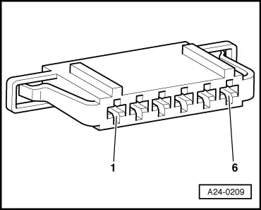
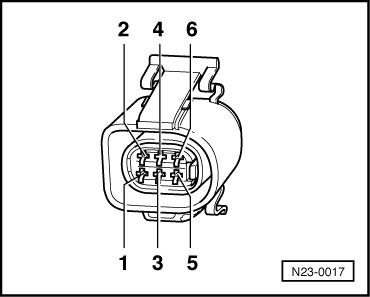
Checking power supply of accelerator pedal position senders

  • ‒ Unplug accelerator pedal position sender connector.

Note:

 
A24-0209

Connector is clipped in at pedal bracket next to brake light switch.

Left-hand drive vehicles:

  • ‒ Switch on ignition.
  • ‒ → Connect portable multimeter for voltage measurement to the following connector sockets:

6-pin connector at wiring harness, socket

Specification

1 + earth

approx. 5 V

1 + 5

approx. 5 V

2 + earth

approx. 5 V

2 + 3

approx. 5 V

Right-hand drive vehicles:

  • ‒ Switch on ignition.
 
N23-0017
  • ‒ → Connect portable multimeter for voltage measurement to the following connector sockets:

6-pin connector at wiring harness, socket

Specification

2 + earth

approx. 5 V

2 + 3

approx. 5 V

5 + earth

approx. 5 V

5 + 4

approx. 5 V

All models:

If readings match specifications:

  • ‒ Additionally check signal wires => Page 24-176.

If readings do not match specifications:

  • ‒ Check wiring between engine control unit and accelerator pedal position senders => Page 24-176.

Checking signal wires and wiring between accelerator pedal position senders and engine control unit

  • ‒ Connect test box V.A.G 1598/31 to engine control unit wiring harness. Actual engine control unit is not to be connected.

Left-hand drive vehicles:

 
A24-0209
  • ‒ → Check for open circuit and short to earth/positive in the following wiring:

Connector,
socket

Test box V.A.G 1598/31,
socket

1

72

2

73

3

36

4 (signal wire)

35

5

33

6 (signal wire)

34

Right-hand drive vehicles:

 
N23-0017
  • ‒ → Check for open circuit and short to earth/positive in the following wiring:

Connector,
socket

Test box V.A.G 1598/31,
socket

1 (signal wire)

35

2

73

3

36

4

33

5

72

6 (signal wire)

34

All models:

  • ‒ If necessary, eliminate open circuit in wiring/short circuit.

If no fault is found in wiring:

  • ‒ Replace accelerator pedal position senders.

=> Fuel Supply System - Petrol Engines; Repair Group 20; Servicing Accelerator Mechanism - Right-hand drive vehicles

Learning kickdown function > < Significance of EPC warning lamp (electric throttle control fault lamp -K132)