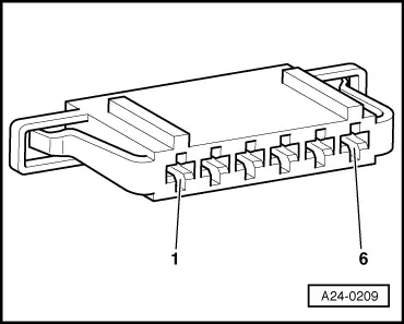
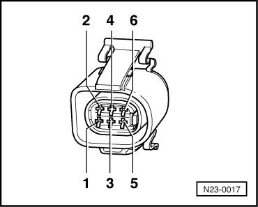
-
‒ Check specifications for electronic throttle system potentiometer voltages.
|
|
|---|
|
|
Display zones
|
|
|
1
|
2
|
3
|
4
|
|
Display group 62: Electronic throttle system potentiometer voltages with ignition on
|
|
Display
|
xx %
|
xx %
|
xx %
|
xx %
|
|
Readout
|
Throttle valve angle
(angle sender 1)
|
Throttle valve angle
(angle sender 2)
|
Accelerator pedal position
sender
|
Accelerator pedal position
sender 2
|
|
Operating range
|
min.: 0 %
max.: 100 %
|
min.: 0 %
max.: 100 %
|
min.: 0 %
max.: 100 %
|
min.: 0 %
max.: 100 %
|
|
Specification
|
3...93 %
|
97...3 %
|
12...97 %
|
4...49 %
|
Note:
The engine control unit converts the angle sender voltage values into percentages referenced to 5 V and displays the percentage values (5 V supply voltage corresponds to 100 %).
-
‒ Observe display zones 3 and 4.
-
‒ Slowly floor accelerator pedal.
The percentage value displayed in zone 3 must increase steadily. The tolerance range 12...97 % is not fully utilised.
The percentage value displayed in zone 4 must likewise increase steadily. The tolerance range 4...49 % is not fully utilised.
Note:
The value displayed in zone 3 must always be roughly twice that in display zone 4.
If displays are not as described:
-
‒ Check power supply and wiring of accelerator pedal position senders .
Checking power supply of accelerator pedal position senders
-
‒ Unplug accelerator pedal position sender connector.
Note:
| 


