audi Workshop Repair Guides

Audi Workshop Service and Repair Manuals

Self Diagnosis > < Connecting fault reader V.A.G 1551 and selecting engine electronics control unit
Motronic injection and ignition system (4-cyl.)
General to self-diagnosis
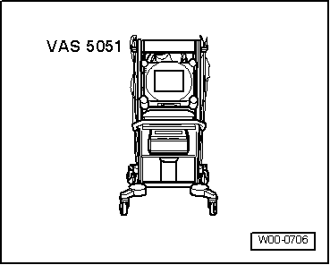
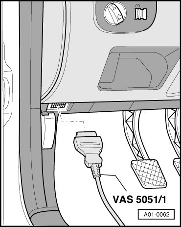
Connecting vehicle diagnosis, testing and information system VAS 5051 and selecting engine control unit
 
W00-0706

All the functions that were previously possible with the V.A.G 1551/1552 can be performed with the new tester VAS 5051 in operating mode Vehicle self-diagnosis:

=> Operating instructions for Vehicle Diagnosis, Testing and Information System VAS 5051.

Special tools, workshop equipment, testers, measuring instruments and auxiliary items required

  • ◆ → VAS 5051 Vehicle Diagnosis, Testing and Information System
  • ◆ Diagnosis cable VAS 5051/1 or VAS 5051/3

Test conditions

  • ● The fuses must be OK.
  • ● Earth connection between engine (on gearbox bell housing) and body (below battery) OK.
  • ● The battery voltage must be at least 11.5 V.
  • ● If the vehicle is equipped with an air conditioning system, this must be switched off.
  • ● All electrical consumers, e.g. lights and rear window heating must be switched off.

Work sequence

 
A01-0062
  • ‒ Connect tester VAS 5051 with diagnosis cable VAS 5051/1 or VAS 5051/3 as follows:
  • ‒ Fit diagnosis cable connector onto diagnosis connector.
  • ‒ Depending on the desired function either switch ignition on
        or
    start engine and run at idling speed. Selectable functions .

Selecting operating mode:

  • ‒ Press button on display for "Vehicle self-diagnosis".

Selecting vehicle system:

  • ‒ Press button "01 - Engine electronics" on display.

The control unit identification and coding are indicated on the display.

If the coding differs from the vehicle version:

  • ‒ Check control unit coding and, if necessary, code engine control unit => Page 24-136

Selecting diagnosis function:

All diagnostic functions available are indicated on the display.

  • ‒ Press button on display for desired function.

Note:

The display zones in functions 04 - Basic setting or 08 - Read measured value block are shown from top to bottom.

  • ‒ Further measures see repair procedures.

Self Diagnosis > < Connecting fault reader V.A.G 1551 and selecting engine electronics control unit