|
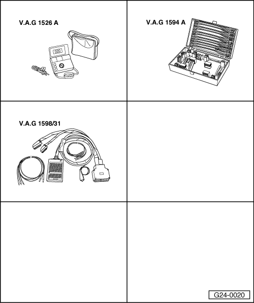
Special tools and workshop equipment required
-
◆ V.A.G 1526 A
-
◆ V.A.G 1594 A
-
◆ V.A.G 1598/31
Test requirements:
-
● Fuses for engine electronics OK
=> Current Flow Diagrams, Electrical Fault-finding and Fitting Locations binder
-
● Battery voltage at least 12.7 V
-
● Alternator OK
Test sequence
-
‒ Connect test box V.A.G 1598/31 to wiring harness for engine control unit; do not connect the engine control unit .
Notes:
-
◆ The positive voltage supply to the engine control unit is provided via contacts 3 and 121 (terminal 15) as well as contact 62 (terminal 30).
-
◆ The earth connection to the engine control unit is provided via contact 1 and contact 2.
-
‒ Connect multimeter as follows to measure voltage:
|
|
|---|
|
Test box V.A.G 1598/31
Socket
|
Measure to
|
|
1
|
Battery positive
|
|
2
|
Battery positive
|
|
62
|
Engine earth
|
-
‒ Specified value: approx. battery voltage
- Connect multimeter as follows to measure voltage:
|
Test box V.A.G 1598/31
Socket
|
Measure to
|
|
3
|
Engine earth
|
|
1211)
|
Engine earth
|
1) The power supply relay for Motronic -J271 carries voltage on terminal 121 of engine control units after switching of the ignition for up to 15 minutes.
-
‒ Switch the ignition on.
-
‒ Specified value: approx. battery voltage
If the specified values are not obtained:
-
‒ Check the wiring connections.
=> Current Flow Diagrams, Electrical Fault-finding and Fitting Locations binder
-
‒ Check power supply relay for Motronic -J271 => Page 28-12.
|