
A3 Mk1
|
Checking ignition system
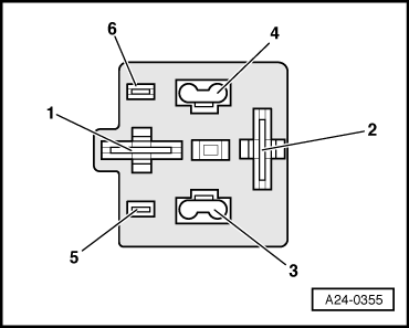
Checking power supply relay for Motronic system -J271
|

 |
|
|
Test sequence
|
 |
|
|
 |
|||||
If specified value is not attained:
|
 |
|
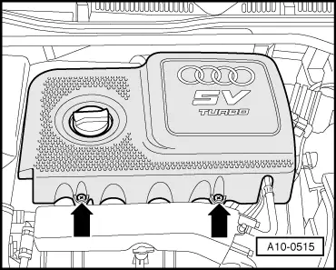
Note: To remove the protective cover in vehicles with dome strut, detach and lower relay holder at the bulkhead. If necessary, unplug connectors from air mass meter. |
 |
||||
If the wiring is OK:
Checking power supply |
|
|
Note: To remove the protective cover in vehicles with dome strut, detach and lower relay holder at the bulkhead. If necessary, unplug connectors from air mass meter. |
|
||||||
If specified value is not attained:
|
 |
|
|
|
|
Note: To remove the protective cover in vehicles with dome strut, detach and lower relay holder at the bulkhead. If necessary, unplug connectors from air mass meter. |
|
|||||
If specified value is not attained:
|
|
|||||
If no fault is found:
|