audi Workshop Repair Guides

Audi Workshop Service and Repair Manuals

4-Cylinder engine (5-valve), Mechanics > < Testing knock sensors
Motronic injection and ignition system (4-cyl. turbo)
Testing ignition system
Testing Hall sender -G163
 
G24-0022

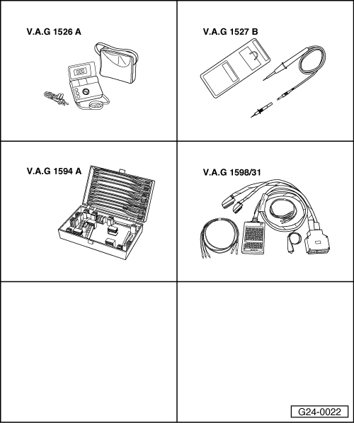
Special tools and workshop equipment required

  • ◆ V.A.G 1526 A
  • ◆ V.A.G 1527 B
  • ◆ V.A.G 1594 A
  • ◆ V.A.G 1598/31

Fitting location => Fitting locations overview, Page 24-5

The Hall sender indicates the ignition position for Cylinder 1.

If the Hall sender fails to function, the knock control is switched off and the ignition timing is retarded slightly because the signals can no longer be assigned to the cylinders.

Even without a signal from the Hall sender the engine will continue to run and can also be re-started.
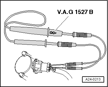
  • ◆ When a fault is detected the engine control unit produces one spark per crankshaft revolution for each cylinder.
  • ◆ The fact that the injection system is one revolution out of phase does not have any noticeable effect on the fuel injection. If this happens, the fuel is injected upstream of the closed inlet valve instead of while the inlet valve is open. This has only a minor influence on the quality of the air/fuel mixture.

Checking activation

  • ‒ Slacken mountings of air intake pipe.
  • ‒ Slide back rubber sleeve (if fitted) on connector for Hall sender but leave connector plugged in.
 
A24-0213
  • ‒ → Connect voltage tester V.A.G 1527 B between contact 2 (Hall sender signal) and contact 1 (positive).

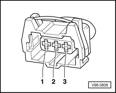
Note:

The connector contacts are numbered on the back of the connector.

  • ‒ Operate starter for a few seconds.
    • ‒ The LED should flash briefly on alternate engine revolutions (i.e. once every two revolutions).

Note:

The LEDs on voltage testers with a low current draw continue to glow faintly between impulses from the engine control unit (rather than going out completely) and become much brighter when receiving an impulse.

If the LED does not flash:

Checking voltage supply

  • ‒ Unplug connector from Hall sender.
 
V96-0836
  • ‒ → Connect multimeter (voltage measurement range) as follows:

Connector
Contact

Measure against

1

Engine earth

  • ‒ Switch on ignition.
    • ‒ Specification: approx. 5 V

Testing signal wire

  • ‒ Connect multimeter (voltage measurement range) as follows:

Connector
Contact

Measure against

2

Engine earth

  • ‒ Switch on ignition.
    • ‒ Specification: approx. battery voltage

Testing earth wire

 
V96-0836
  • ‒ → Test for open circuit and short to positive in the following wiring connection:

Connector
Contact

Measure against

3

Engine earth

  • ‒ Rectify any open/short circuit as necessary.

If all the readouts match the specifications but the LED does not flash (measurement taken between contacts 1 and 2 without unplugging connector and while operating starter):

  • ‒ Renew the Hall sender.

If the specifications are not obtained:

Testing wiring between Hall sender and engine control unit

  • ‒ Connect test box V.A.G 1598/31 to wiring harness for engine control unit. Do not connect to the engine control unit itself.
    .
 
V96-0836
  • ‒ → Test for open circuit and short to positive or earth in the following wiring connections:

Connector
Contact

Test box V.A.G 1598/31
Socket

1 (positive)

98

2 (signal)

86

3 (earth)

108

  • ‒ Rectify any open/short circuit as necessary.
  • ‒ If all the test results so far have been OK but a fault relating to the camshaft sensor (Hall sender) is displayed again after erasing the fault memory as a test measure, the cause may be as follows:
    • ‒ Rotor ring on Hall sender out of position
  • ‒ Unbolt Hall sender, then check to ensure that the rotor ring is correctly aligned on the camshaft. If incorrectly installed, the catch will be pressed flat when the securing screw is tightened.
  • ‒ If the rotor ring is correctly aligned, check the position of the camshaft in relation to the crankshaft.

=> 4-Cylinder engine (5-valve turbo), Mechanics; Repair Group 15; Cylinder head, valve gear; Removing and installing camshafts

4-Cylinder engine (5-valve), Mechanics > < Testing knock sensors