
A3 Mk1
 |
|
|
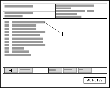
→ Display on VAS 5051:
|
 |
|
|
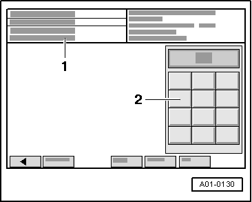
→ Display on VAS 5051:
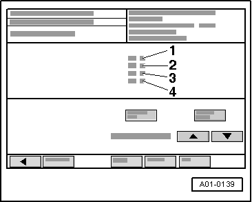
Note: The measured value blocks 125 and 126 indicate CAN drive users.
|
 |
|
|
→ Display on VAS 5051:
|
|
|
→ Display on VAS 5051:
|
 |
|||||||||
=> Current Flow Diagrams, Electrical Fault-finding and Fitting Locations binder
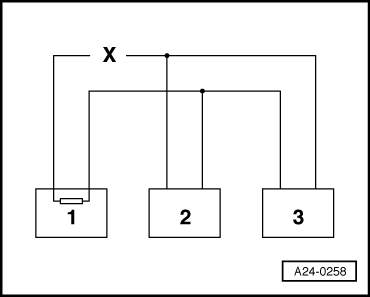
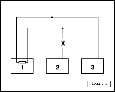
Example 2: The faults stored in the fault memories indicate that the control unit 2 does not communicate with control units 1 and 3. |
 |
||||||||||||||||||
=> Current Flow Diagrams, Electrical Fault-finding and Fitting Locations binder
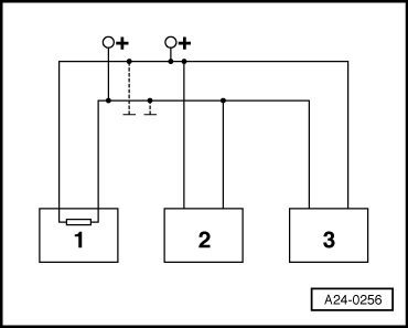
Example 3: The faults stored in the fault memories indicate that sending or receiving is not possible in any of the control units.
|
 |
|
=> Current Flow Diagrams, Electrical Fault-finding and Fitting Locations binder If cause of fault "Data bus drive defective" cannot be found in bus lines check whether one of the control units is responsible for the fault. Test requirements:
All the control units that communicate via the CAN data bus are still disconnected. Ignition is switched off.
|
 |
|
|
→ Display on VAS 5051:
|