
A3 Mk1
 |
|
|
→ Display on VAS 5051:
If the injector does not click:
If valve does not open or close properly:
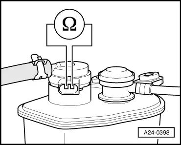
Checking internal resistance
|
 |
||||
If the LED does not illuminate:
=> Current Flow Diagrams, Electrical Fault-finding and Fitting Locations binder
If the LED illuminates:
Checking actuation |
|
|
If the LED lamp does not flash or if it illuminates continuously:
|
|
||||
If the wiring is OK:
|