
A3 Mk1
|
Servicing Motronic injection system
Checking air mass meter -G70
|
 |
|
|
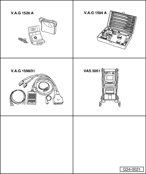
Special tools and workshop equipment required
Fitting location => Fitting locations overview, Page 24-5 Test requirements:
Checking function
|
 |
|
|
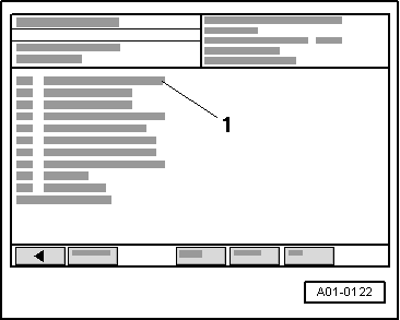
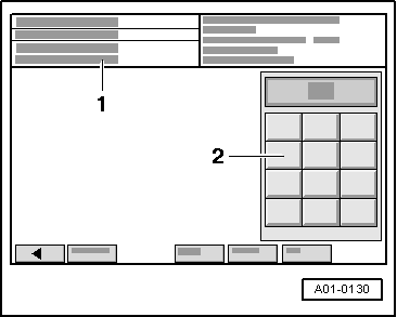
→ Display on VAS 5051:
|
 |
|
|
→ Display on VAS 5051:
|
 |
|||||||||||||||||||||||||||||||||||||||||||||||||||||||||||||||
|
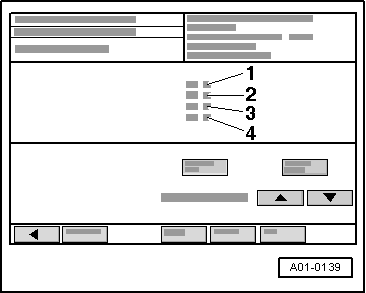
→ Display on VAS 5051:
If specified value is attained:
Evaluation of display group 002
Checking voltage supply to air mass meter Test requirements:
=> Current Flow Diagrams, Electrical Fault-finding and Fitting Locations binder
Note: Voltage supply to air mass meter is from fuel pump relay.
| |||||||||||||||||||||||||||||||||||||||||||||||||||||||||||||||
 |
||||
If specified value is not attained:
=> Current Flow Diagrams, Electrical Fault-finding and Fitting Locations binder
|
|
|
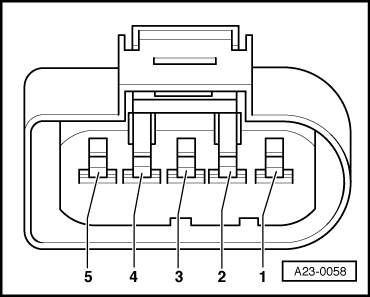
Note: Engine control unit earth is present at contact 3 of the connector. If specified value is not attained:
|
|
|
If specified value is not attained:
Checking wiring to air mass meter. Note: The signal wire is also checked during the wiring check.
|
|
|||||||||
If the wiring is OK:
|