audi Workshop Repair Guides

Audi Workshop Service and Repair Manuals

Testing lambda probe heating > < Operation of lambda control
Motronic injection and ignition system (4-cyl. turbo)
Testing lambda control
Testing lambda probe and lambda control
 
G24-0021

Special tools and workshop equipment required

  • ◆ V.A.G 1526 A
  • ◆ V.A.G 1594 A
  • ◆ V.A.G 1598/31
  • ◆ VAS 5051 with VAS 5051/1
  • or
  • ◆ V.A.G 1551 with V.A.G 1551/3 A

Notes:

  • ◆ For the purposes of fault-finding it is possible to switch off the lambda control by selecting Display Group 099 in "Basic setting" mode and to switch it on again by selecting Display Group 099 in "Read measured value block" mode.
  • ◆ After selecting Display Group 099 (either in "Basic setting" mode or in "Read measured value block" mode) it is possible to switch back and forth between function 04 ("Basic setting") and function 08 ("Read measured value block") by pressing keys 4 and 8 on fault reader V.A.G 1551.
  • ◆ When exiting the "Basic setting" mode (function 04) the lambda control is automatically switched on again.
  • ◆ The 4-pin connector for lambda probe 1 -G39 and lambda probe heating -Z19 is located on the right side of the bulkhead => -Item 24-5.

Requirements for test:

  • ● Take the car for a test drive and do not erase the fault memory.
  • ● Coolant temperature at least 80 °C

Testing operation

  • ‒ Connect vehicle diagnostic, testing and information system VAS 5051 (or fault reader V.A.G 1551) and select engine electronics control unit by entering address word "01" ( .)
    When doing this the engine must be idling.
 
→ Indicated on display:
Rapid data transfer     HELP
Select function XX
  • ‒ Enter "04" to select "Basic setting" and confirm with Q key.

Note:

During the basic setting the activated charcoal filter solenoid valve (ACF valve -N80) is closed and the air conditioner compressor is switched off.

 
→ Indicated on display:
Introduction of basic setting    Q
Enter display group number XXX
  • ‒ Enter "030" to select Display Group 030 and confirm entry with Q key.
 
→ Indicated on display:
Basic setting 30    ⇒
    1    2    3    4
  • ‒ Check lambda probe status in display zone 1.

Note:

The "lambda probe status" display indicates the status of the lambda control and lambda probes.

Display zones

1

2

3

4

Display Group 030: Lambda probe status

Display

X X X

Indicates

Lambda probe status Bank 1

Range

0 = off
1 = on


Specification

1 1 1

Note

If readout does not match specification => Page 24-72.

Relevance of 3-figure display in Display Group 030

X

X

X

Display zone 1

1

Lambda control active

1

Lambda probe condition

1

Status of lambda probe heating

Testing lambda probe learned values and lambda control

  • ‒ Press C key.
  • ‒ Enter "032" to select Display Group 032 and confirm entry with Q key.
 
→ Indicated on display:
Basic setting 32    ⇒
    1    2    3    4
  • ‒ Check readouts for lambda control in display zones 1 and 2.

Display zones

1

2

3

4

Display Group 032: Lambda learned values

Display

xx.x %

xx.x %

Indicates

Lambda learned value, Bank 1 at idling speed (additive)

Lambda learned value, Bank 1 at part throttle (multiplicative)

Range

-25.0...25.0 %

-25.0...25.0 %


Specification

-10.0...10.0 %
(slight fluctuation
possible)

-10.0...10.0 %
(slight fluctuation
possible)


Note

If the specification is not attained

  • ‒ Press C key.
  • ‒ Enter "033" to select Display Group 033 and confirm entry with Q key.
 
→ Indicated on display:
Basic setting 33    ⇒
    1    2    3    4
  • ‒ Check readouts for lambda control in display zones 1 and 2.

Display zones

1

2

3

4

Display Group 033: Lambda control

Display

xx.x %

x.xxx V

Indicates

Lambda control
Bank 1

Lambda probe voltage Bank 1

Range

-25.0...25.0 %

0.000...1.000 V


Specification

Between -10.0 and 10.0 % the readout should fluctuate by at least 2 %

Between 0.000 and 1.000 V the voltage should fluctuate by about 0.3 V

Note

If readout does not match specification
=>Further notes,
Page 24-75

If readout does not match specification
=>Reading Display Group 033, Page 24-78

Further notes

If the readout in display zone 1 does not match the specification, or if the readout does not fluctuate by at least 2 %:

  • ‒ Take car for a test drive to free lambda probe of any deposits, then repeat the test.

If the readout in display zone 1 still does not match the specification even after the test drive, or if the readout still does not fluctuate by at least 2 %:

  • ‒ Test the basic voltage => Page 24-79.
  • ‒ Test the lambda probe heating=> Page 24-81.

Reading Display Group 032

Display zone 1 / 2

Possible cause of fault

Fault remedy

Lambda learned
values between
-10.0 and -25.0 %

- Air leak in intake system (pressure side between turbocharger and intake manifold)

- Check intake system for leaks and eliminate unmetered air
=> Page 24-63

- Oil dilution

- Change oil or drive car
at moderate to high speeds on
out-of-town roads

- High oil consumption

- Air mass meter defective

- Test air mass meter
=> Page 24-55

- Solenoid valve for activated charcoal filter sticking in open position

- Test solenoid valve for activated
charcoal filter => Page 24-105

- Fuel pressure too high

- Test fuel pressure regulator
=> Page 24-26

- Injector leaking

- Test injectors => Page 24-32

- Lambda probe heating defective
- Lambda probe dirty

- Test lambda probe heating
=> Page 24-81

Reading Display Group 032

Display zone 1 / 2

Possible cause of fault

Fault remedy

Lambda learned
values between
10.0 and 25.0 %

- Unmetered air in intake tract

- Check intake system for leaks and eliminate unmetered air
=> Page 24-63

- Fuel pressure too low

- Test fuel pressure regulator
=> Page 24-26

- Lambda probe heating defective

- Test lambda probe heating
=> Page 24-81

- Injector not opening or only opening partially

- Test injectors => Page 24-32

- Solenoid valve for activated charcoal filter sticking

- Test solenoid valve for activated
charcoal filter => Page 24-105

Reading Display Group 033

Display zone 2

Possible cause of fault

Fault remedy

Approx. 0.450 V (constant)

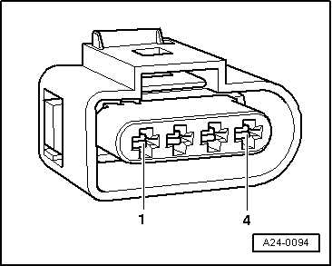
- Open circuit in wire 4 between lambda probe and control unit

- Test basic voltage => Page 24-79

- Open circuit in wire 3 between lambda probe and control unit

Approx. 0.200 V
(constant)

- Lambda probe defective

- Renew lambda probe

More than 1.100 V

- Short to positive in wire 4 between lambda probe and control unit

- Test lambda probe wiring => Page 24-80

Less than 0.150 V

- Short to earth in wire 4 between lambda probe and control unit

Testing basic voltage

 
A24-0292
  • ‒ → Unplug 4-pin connector -arrow- for lambda probe.

Note:

Re-fit the heat shield sleeve on the connector after completing the test.

 
A24-0094
  • ‒ → Connect multimeter (voltage measurement range) between contacts 3 and 4.
  • ‒ Switch ignition on.
    • ‒ Specification: 0.400 ... 0.500 V
  • ‒ Switch off ignition.

If the specification is not obtained:

  • ‒ Test lambda probe wiring.

If the specification is obtained:

  • ‒ Renew the lambda probe.
 
A24-0292

Testing lambda probe wiring

  • ‒ → Unplug 4-pin connector -arrow- for lambda probe.

Note:

Re-fit the heat shield sleeve on the connector after completing the test.

  • ‒ Connect test box V.A.G 1598/31 to wiring harness for engine control unit. Do not connect to the engine control unit itself.
    => Page 24-16.
 
A24-0094
  • ‒ → Test the following wiring connections for open circuits:

Connector
Contact

Test box V.A.G 1598/31
Socket

3

51

4

70

  • ‒ Rectify any open circuits.
  • ‒ Test for short circuits between the wires.

If the wiring is OK:

  • ‒ Fit a new engine control unit => Page 24-18.

Testing lambda probe heating > < Operation of lambda control