audi Workshop Repair Guides

Audi Workshop Service and Repair Manuals

Checking clutch pedal switch F36 > < Adapting kickdown function
Checking brake light switchF and brake pedal switchF47
Checking brake light switch -F- and brake pedal switch -F47-
Special tools and workshop equipment required
t  -V.A.G 1526 A-
t  -V.A.G 1527 B-
t  -V.A.G 1594 A-
t  -V.A.G 1598/31-
   
t  
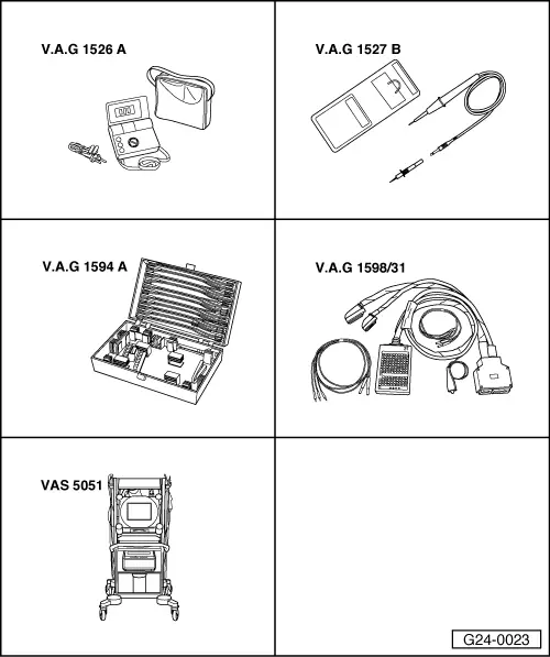
Vehicle diagnosis and service information system -VAS 5052-
Test sequence
  Note
For safety reasons, the signal from the accelerator position sender (potentiometer) instructing the engine control unit to open the throttle valve is suppressed whenever the brake is operated. To do this the control unit requires signals from the brake light switch and also the brake pedal switch. If the brake is operated while the accelerator is held constantly depressed, the engine is immediately governed down to idling speed. A defective switch can cause unwanted governing of engine speed.
–  Connect up the vehicle diagnostic and service information system -VAS 5052- and select the engine electronics control unit. When doing this, the ignition must be switched on.
–  Select the function “Read measured value block”.
–  Select “Display group number 066”.
–  Check the brake light/brake pedal switch in display zone 2.
  G24-0023
 Display zones
 1234
Display group 066: Signals to engine control unit
Displayxxx km/hXXXXXXXXxxx km/hXXXXXXXX
DisplayACTUAL vehicle speedSwitch positionsSPECIFIED vehicle speedSwitch positions
Operating range XXXXXX00
XXXXXX11
  
Specification 
l  Pedal not pressed:
XXXXXX00
  
  
l  Pedal pressed:
XXXXXX11
  
Note Value:
X = no significance.
The switching points are slightly offset
  

If display differs from specification described above: check switch
Checking switch
–  Remove driver's storage compartment → Rep. Gr.68.
–  Unplug the connector at the brake light/brake pedal switch.
   
–  Connect up the multimeter (resistance measuring range) between contacts 1 and 4.
t  Specification: ∞ Ω (no continuity)
–  Depress the brake pedal.
t  Specification: approx. 0 Ω
–  Connect up the multimeter (resistance measuring range) between contacts 2 and 3.
t  Specification: approx. 0 Ω
–  Depress the brake pedal.
t  Specification: ∞ Ω (no continuity)
If the readings do not match the specifications:
–  Replace the brake light switch/brake pedal switch.
If the specifications are obtained:
–  Check voltage supply.
Checking voltage supply
  A24-0210
–  Connect up the voltage tester -V.A.G 1527 B- as follows:
  A24-0200
Connector
Contact
Measure to
1Body earth

t  The LED must light
   
Connector
Contact
Measure to
2Body earth

–  Switch on ignition.
t  The LED must light
If the LED does not light:
–  Check for open circuit/short to earth in the wiring from contacts 1/2 of the connector.
–  Eliminate open circuit in wiring/short circuit if necessary.
If the LED lights:
–  Check actuation.
Checking activation
–  Connect the test box -V.A.G 1598/31- to the wiring harness to the engine control unit, but do not connect the actual engine control unit → Chapter.
   
–  Check for open circuit and short to earth or positive in the following wiring:
  A24-0200
Connector
Contact
Test box -V.A.G 1598/31-
Socket
355
456

–  Eliminate open circuit in wiring/short circuit if necessary.
   

Checking clutch pedal switch F36 > < Adapting kickdown function