audi Workshop Repair Guides

Audi Workshop Service and Repair Manuals

Removing and installing engine control unit with and without protective housing > < The following procedure applies to engine control units which are not bolted to a protective housing by way of a locking element
Procedure for engine control units bolted to a protective housing
  Note
t  The test box -V.A.G 1598/31- is designed such that it can be simultaneously connected to both the wiring harness to the engine control unit and to the engine control unit itself.
t  This has the advantage that the electronic engine management system remains fully functional with the test box connected (e.g. for measurement of signals with engine running).
t  Whether or not the engine control unit is additionally to be connected to the test box is described in the relevant test procedures.
t  Use is always to be made for connecting measuring instruments (e.g. voltage tester -V.A.G 1527B-, portable multimeter -V.A.G 1526C-) of the adapter set -V.A.G 1594C-.
Special tools and workshop equipment required
t  Hot air blower -1- (from wiring harness repair set -VAS 1978A-)
   
t  Commercially available vice-grip pliers
–  Switch off ignition.
–  Unscrew the wiper arms.
–  Detach the plenum chamber cover and set it down towards the windscreen.
  Note
  A24-0475
Item -1- in the illustration shows the engine control unit with protective housing.
  A24-0540
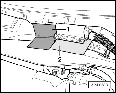
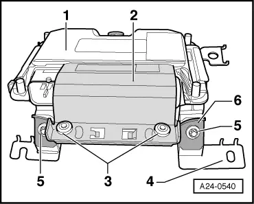
To make the connectors at the engine control unit less accessible, the engine control unit -1- is bolted to a protective housing -4- by means of a locking element -2- and shear bolts -3-.
To make it even more difficult to screw out the shear bolts, the threads are coated with locking fluid.
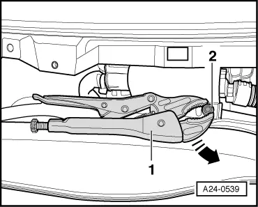
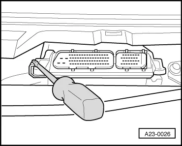
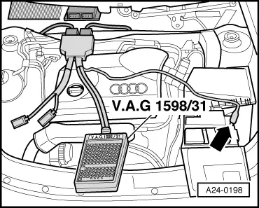
The locking element -2- must be separated from the protective housing to enable the connectors to be unplugged from the engine control unit (e.g. when connecting the test box). This procedure is described in the following.
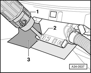
  WARNING
Exact compliance with the following operations is essential so as not to damage (scorch) wiring, connectors, insulation and control units. Heed the operating instructions for the hot air blower.
  A24-0540
So as to avoid damaging wires and connectors, fit plates to provide a screen (items -1- and -2-). This is designed to stop the connector housing and wiring harness becoming hot.
  A24-0538
–  Select the settings on the hot air blower as shown in the illustration, i.e. set the temperature potentiometer -2- to maximum heat output and the two-stage air flow switch -3- to position 3.
  Note
Then heat the bolt of the locking element with the hot air blower. This step reduces the inhibiting action of the locking fluid on the shear bolt threads, making these easier to unscrew.
  WARNING
The shear bolts and parts of the metal housing also become very hot when heating the thread of the locking element. Take care to avoid burns. It is also important to ensure that only the thread is heated and none of the surrounding components if at all possible. These should be covered if necessary.
  A24-0476
–  Direct nozzle -1- of hot air blower at bolt -2- of locking mechanism.
  Note
Particular care is to be taken in this case as the control unit connectors are in the immediate vicinity.
–  Switch on the hot air blower and heat the thread for about 20 to 25 seconds.
  A24-0537
–  Then grasp the head of the bolt -2- with the vice-grip pliers -1- and unscrew the shear bolt in arrow direction.
–  To enhance anti-theft protection, the locking element is mounted such that it is not possible to give the vice-grip pliers a full turn.
The procedure for the second shear bolt is exactly the same. Particular care is to be taken in this case as the control unit connectors are in the immediate vicinity.
–  After taking out the second bolt, the locking element for the connectors can be removed.
  A24-0539
–  Use a screwdriver to press aside the retainer tab of the mount and pull out the engine control unit to the front.
–  Release the connector catches and unplug the control unit connectors.
  A23-0026
–  Connect the test box -V.A.G 1598/31- to the wiring harness connectors. Connect the earth clip at the test box (not visible in illustration) to earth. Whether or not the engine control unit is additionally to be connected to the test box is described in the relevant test procedures.
–  Perform testing as described in the appropriate repair procedures.
Perform the following operations after re-connecting the engine control unit:
Install accordingly in the reverse order of removal. The protective housing (locking element) is to be re-attached to the engine control unit. Use is to be made of new shear bolts.
–  Bend back the retainer tab of the mount.
  Note
t  The following operations must be performed after re-connecting the engine control unit:
t  Adaption of throttle valve module -J338-
t  Kick-down function adaption for vehicles with automatic gearbox
t  Interrogation and (if applicable) erasing of fault memory.
Procedure following interruption of voltage supply
  Note
t  The following operations must be performed after re-connecting the voltage supply:
t  Adaption of throttle valve module -J338- → Chapter
t  Kick-down function adaption for vehicles with automatic gearbox → Chapter
t  Interrogation and (if applicable) erasing of fault memory → Chapter
  Note
Slightly rough idling and slight bucking whilst driving may be encountered in the initial adaption phase.
  A24-0198

Removing and installing engine control unit with and without protective housing > < The following procedure applies to engine control units which are not bolted to a protective housing by way of a locking element