
A3 Mk1
| Overview of fitting locations |
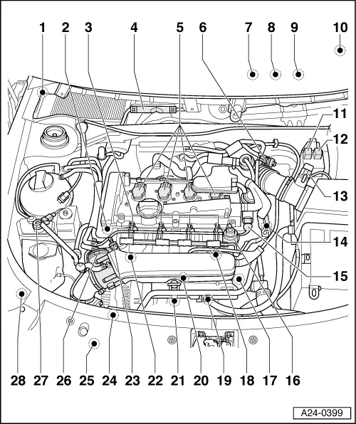
| 1 - | Lambda probe -G39- with Lambda probe heater -Z19- |
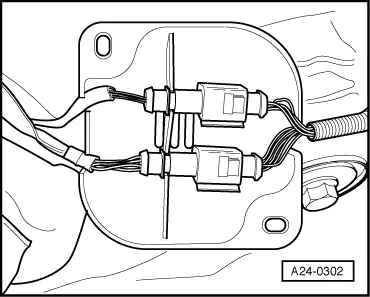
| q | For fitting locations of Lambda probes and protective cover for connectors, refer to → Fig., → Fig. |
| q | For marking of connectors for Lambda probes, refer to → Fig., → Fig. |
| q | Checking Lambda probe and lambda control upstream of catalytic converter → Chapter |
| q | Checking for ageing of Lambda probe upstream of catalytic converter → Chapter |
| q | Checking heating for Lambda probe upstream of catalytic converter → Chapter |
| q | Removing and installing → Chapter |
| 1 - | Lambda probe, after catalytic converter -G130- with Lambda probe heater 1, after catalytic converter -Z29- |
| q | For fitting locations of Lambda probes and protective cover for connectors, refer to → Fig. |
| q | For marking of connectors for Lambda probes, refer to → Fig., → Fig. |
| q | Checking Lambda probe and lambda control downstream of catalytic converter → Chapter |
| q | Checking heating for Lambda probe downstream of catalytic converter → Chapter |
| q | Removing and installing → Chapter |
| 2 - | Hall sender -G40- |
| q | Checking → Chapter |
| 3 - | Injector, cylinder 1 -N30- ...injector, cylinder 4 -N33- |
| q | Checking → Chapter |
| q | Removing and installing → Chapter |
| 4 - | Motronic control unit -J220- |
| q | Checking voltage supply of engine control unit → Chapter |
| q | Replacing → Chapter |
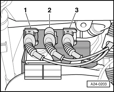
| 5 - | Ignition coil 1 with output stage -N-, ignition coil 2 -N128-, ignition coil 3 -N158-, ignition coil 4 -N163- |
| q | Checking → Chapter |
| 6 - | Solenoid valve for charge pressure control -N75- |
| q | Checking: 4-cylinder engine (5-valve turbo), mechanics → Rep. Gr.21 |
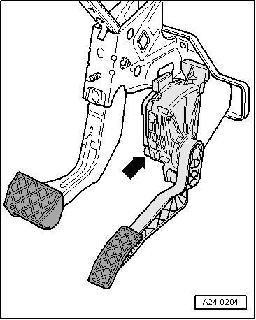
| 7 - | Accelerator pedal position sender -G79- and accelerator pedal position sender 2 -G185- |
| q | Fitting location → Fig. |
| q | Checking → Chapter |
| q | Kick-down function adaption for vehicles with automatic gearbox → Chapter |
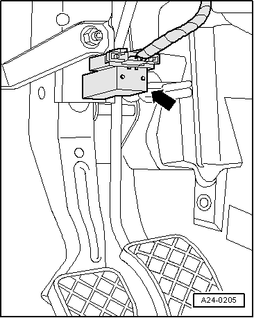
| 8 - | Brake light switch -F- and brake pedal switch -F47- |
| q | Fitting location → Fig., → Fig. |
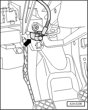
| 9 - | Clutch pedal switch -F36- |
| q | Fitting location → Fig., → Fig. |
| 10 - | Instrument cluster |
| q | With electronic power control fault lamp -K132- (“EPC” warning lamp) Notes on EPC warning lamp → Chapter |
| q | With exhaust emissions warning lamp -K83-. Notes on exhaust emissions warning lamp → Chapter |
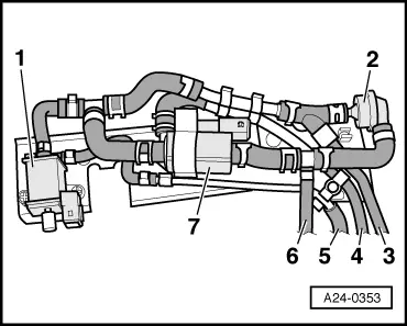
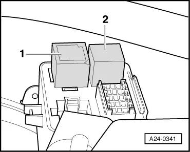
| 11 - | Motronic current supply relay -J271- |
| q | Fitting location → Fig., → Fig. |
| q | Checking → Chapter |
| 12 - | Secondary air pump relay -J299- |
| q | Fitting location → Fig., → Fig. |
| q | Checking: → 4-cylinder engine (5-valve turbo), mechanics; Rep. Gr. 26; Checking secondary air system |
| 13 - | Air mass meter -G70- |
| q | Checking → Chapter |
| 14 - | Coolant temperature sender -G62- |
| q | Checking → Chapter |
| q | If necessary release pressure in cooling system before removing |
| 15 - | Inlet camshaft timing adjustment valve 1 -N205- 4-cylinder engine (5-valve turbo), mechanics → Rep. Gr.15 |
| 16 - | Fuel pressure regulator |
| q | Checking → Chapter |
| 17 - | Engine speed sender -G28- |
| q | Checking → Chapter |
| 18 - | Knock sensor 2 -G66- |
| 19 - | Turbocharger air recirculation valve -N249- |
| q | Fitting location → Fig., → Fig. |
| q | Checking: 4-cylinder engine (5-valve turbo), mechanics → Rep. Gr.21 |
| 20 - | 3-pin connector |
| q | 3 x |
| q | Fitting location → Fig., → Fig. |
| q | For knock sensor 1 -G61- |
| q | For engine speed sender -G28- |
| q | For knock sensor 2 -G66- |
| 21 - | Secondary air inlet valve -N112- |
| q | Fitting location → Fig., → Fig. |
| q | Checking: 4-cylinder engine (5-valve turbo) → Rep. Gr.26 |
| 22 - | Knock sensor 1 -G61- |
| 23 - | Intake air temperature sender -G42- |
| q | Checking → Chapter |
| 24 - | Secondary air pump motor -V101- |
| q | Checking: 4-cylinder engine (5-valve) → Rep. Gr.26 |
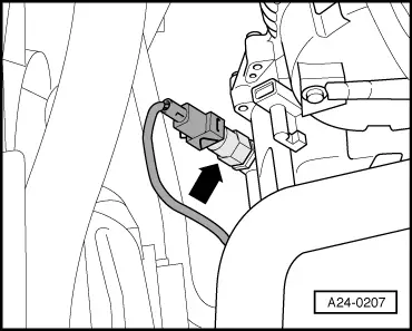
| 25 - | Power steering pressure switch -F88- |
| q | Fitting location → Fig., → Fig. |
| 26 - | Throttle valve module -J338- |
| q | With throttle valve drive (electric power control) -G186-, throttle valve drive angle sender 1 (electric power control) -G187- and throttle valve drive angle sender 2 (electric power control) -G188- |
| q | Checking → Chapter |
| q | Perform adaption after renewal → Chapter |
| 27 - | Activated charcoal filter solenoid valve 1 -N80- |
| q | Checking → Chapter |
| 28 - | Charge air pressure sender -G31- |
| q | Screwed into top of charge air cooler |
| q | Checking: 4-cylinder engine (5-valve turbo), mechanics → Rep. Gr.21 |
 Note
Note
|
|
|
|
|
|
| Black connector | For Lambda probe -G39- and Lambda probe heater -Z19- |
| Brown connector | For Lambda probe after catalytic converter -G130- and Lambda probe 1 heater after catalytic converter -Z29- |
|
|
|
|
|
|
|
|
|
|