audi Workshop Repair Guides

Audi Workshop Service and Repair Manuals

Basic setting > < Fault table
TDI Injection and Glow Plug System (4-cyl.) 08.99 >
Self-diagnosis
Final control diagnosis

Test requirements for vehicles with air -conditioners

  • ● Vehicle at room temperature (warmer than + 15 °C)
  • ● Air conditioner switched on
  • ● Lowest temperature and fastest fan speed selected

The final control diagnosis activates the following components in the stated order:

1. Injection start valve (N108)

2. Valve for exhaust gas recirculation (N18)

3. Air conditioner compressor cut-in

4. Fuel cut-off valve (N109)

5. Solenoid valve for boost pressure limitation (N75)

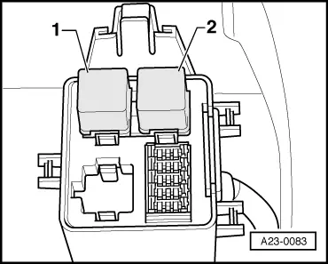
6. Glow plug relay (J52)

7. Glow period warning lamp (K29)

8. Low heating output relay (J359)

  • only in vehicles with manual gearboxes

9. High heating output relay (J360)

  • only in vehicles with manual gearboxes

10. Blower relay (J323)

  • engine codes AHF and ASV only
  • ‒ Connect vehicle diagnostic, testing and information system VAS 5051 or fault reader V.A.G 1551 and select engine electronics control unit with "Address word" 01 .
    For this purpose, the engine should be idling.
 
→ Indicated on display:
Rapid data transfer     HELP
Select function XX
  • ‒ Press keys 0 and 3 for "Final control diagnosis" function
 
→ Indicated on display:
Rapid data transfer     Q
03 - Final control diagnosis
  • ‒ Confirm input with Q key.
 
→ Indicated on display:
Final control diagnosis    ⇒
Injection start valve -N108
  • Valve actuation has a considerable effect on combustion noise (pre ignition).

If no change in the combustion noise is heard:

  • ‒ Check the injection timing control range
    .
  • ‒ Press ⇒key.
 
→ Indicated on display:
Final control diagnosis    ⇒
Exhaust gas recirculation valve -N18
  • The injector valve should click.

Notes:

  • ◆ Due to the engine noise, the clicking of the valve is not audible and therefore may only be detected by feeling.

If the valve does not click:

  • ‒ Check exhaust gas recirculation valve.

=> 4-cyl. Diesel Direct Injection System (TDI), Mechanical Components; Repair group 26

  • ‒ Press ⇒key.
 
→ Indicated on display:
Final control diagnosis    ⇒
Air conditioner compressor cut-in
  • Check the air conditioner compressor shutoff.
  • This test step is also invoked for vehicles without air conditioners.
  • The air conditioning conditioner compressor must stop within 5 secs. (visual check), and then start approx. every 5 secs. and then stop again.

If the air conditioner compressor is not switched off:

  • ‒ Check the air conditioner compressor shutoff
    .
  • ‒ Press ⇒key.
 
→ Indicated on display:
Final control diagnosis    ⇒
Fuel cut-off valve -N109
  • The engine must stop.

If the engine does not stop:

  • ‒ Switch ignition off.
  • ‒ Unscrew the fuel cut-off valve and remove any metallic parts or dirt
  • ‒ Repeat final control diagnosis and if the engine will still not stop, replace the fuel cut off valve.
  • ‒ Press ⇒key.
 
→ Indicated on display:
Final control diagnosis    ⇒
Boost pressure limitat. solenoid valve -N75
  • The solenoid valve must click.

Note:

The clicking of the valve is difficult to hear and is therefore best checked by touch.

If the solenoid valve does not click:

  • ‒ Check boost pressure control solenoid valve.

=> 4-cyl. Diesel Direct Injection System (TDI), Mechanical Components; Repair group 21

  • ‒ Press ⇒key.
 
→ Indicated on display:
Final control diagnosis    ⇒
Glow plug relay -J52
  • The relay must click.
  • Due to the high current consumption, the switching on and off of the relay may also be observed from the interior light becoming brighter and darker.

If the relay does not click:

  • ‒ Check the glow plug relay:

=> Current Flow Diagrams, Electrical Fault-finding and Fitting Locations binder

  • ‒ Press ⇒key.
 
→ Indicated on display:
Final control diagnosis    ⇒
Glow period warning lamp -K29
  • The warning lamp must blink.

Warning lamp does not blink:

  • ‒ Check glow period warning lamp.

=> Current Flow Diagrams, Electrical Fault-finding and Fitting Locations binder

  • ‒ Press ⇒key.
 
→ Indicated on display:
Final control diagnosis    ⇒
Low heating output relay (J359)
  • The relay must click.

If the relay does not click:

  • ‒ Test low heating output relay:

=> Current Flow Diagrams, Electrical Fault-finding and Fitting Locations binder

  • ‒ Press ⇒key.
 
→ Indicated on display:
Final control diagnosis    ⇒
-J360 high heating output relay
  • The relay must click.

 
A23-0083

If the relay does not click:

  • ‒ Test high heating output relay

=> Current Flow Diagrams, Electrical Fault-finding and Fitting Locations binder

→ Fitting location Relay box on bulkhead

-1- Low heating output relay
-2- High heating output relay

  • ‒ Press ⇒key.
 
→ Indicated on display:
Final control diagnosis    ⇒
Blower relay -J323

Engine codes AHF and ASV only

  • Radiator fan must switch on every 5 seconds and then stop again

If the radiator fan does not start:

  • ‒ Check radiator fan after-run control unit -J138

=> Current Flow Diagrams, Electrical Fault-finding and Fitting Locations binder

Note:

The radiator fan may also be activated by the thermoswitch, the automatic gearbox or the air conditioner. When performing the final control diagnosis, ensure that the fan has not been actuated for these reasons.

  • ‒ If necessary, allow engine to cool down.
 
→ Indicated on display:
Rapid data transfer     HELP
Select function XX
  • ‒ Press keys 0 and 6 for the "End output" function and press the Q key to confirm entry.

Basic setting > < Fault table