
A3 Mk1
 |
|
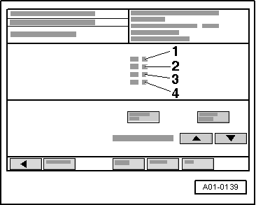
→ Display on VAS 5051:
|
 |
|||||||||
|
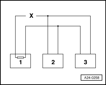
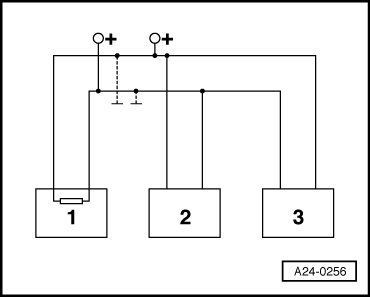
Example 1: From the faults present in the fault memories, you can see that control unit 1 has no connection to control units 2 or 3.
=> Current flow diagrams, Electrical fault finding and Fitting locations binder
|
 |
|||||||||
|
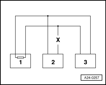
Example 2: From the faults present in the fault memories, you can see that control unit 2 has no connection to control units 1 or 3.
=> Current flow diagrams, Electrical fault finding and Fitting locations binder
|
 |
|||||||||
|
Example 3: From the faults present in the fault memories, you can see that none of the control units are able to transmit or receive signals.
=> Current flow diagrams, Electrical fault finding and Fitting locations binder If the cause of the fault "Data bus drive defective" cannot be found in the data bus wires, check whether one of the control units is causing the fault. At this stage all the control units which communicate via the CAN data bus are disconnected. The ignition is switched off.
|