
A3 Mk1
|
Testing control unit input values
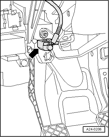
Testing clutch pedal switch -F36
Note: This signal is used to avoid over-revving and load change jolts when disengaging the clutch. It is also needed for the cruise control system. |
 |
|
|
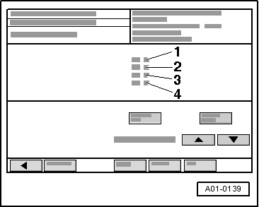
Test sequence
→ Display on VAS 5051:
|
 |
|
|
If the specifications are not obtained: Testing switches
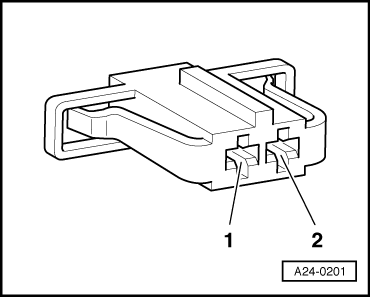
Switch with 2-pin connector:
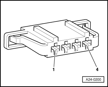
Switch with 4-pin connector:
All models
If the specifications are not obtained:
|
 |
||||
|
If the specifications are obtained: Testing voltage supply
→ Switch with 2-pin connector:
|
|
||||
|
→ Switch with 2-pin connector:
|
 |
||||
|
→ Switch with 4-pin connector:
All models
If no fault is found:
|