audi Workshop Repair Guides

Audi Workshop Service and Repair Manuals

Servicing drive shaft with triple roller joint AAR 2000 > < Removing and installing drive shafts
Running gear, Front-wheel drive and four-wheel drive
Servicing front drive shafts
Servicing front drive shaft with constant velocity joint

Grease fill of joints

Grease

Outer joint ø

Inner joint ø

G 000 603

81 mm

90 mm

94 mm

100 mm

Total quantity


80 g


120 g


90 g


120 g

In joint

40 g

80 g

40 g

50 g

In boot

40 g

40 g

50 g

70 g

Note:

Re-grease joint on replacing boot.

 
A40-0442

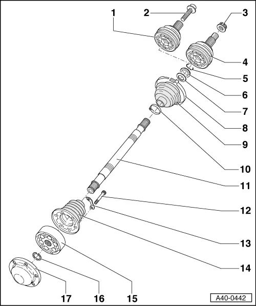
Exploded view of components

  • Outer constant velocity joint
    • ◆ Replace only as complete assembly
    • ◆ Checking
    • ◆ Removing => Fig.2
    • ◆ Greasing =>Table, Page 40-148
    • ◆ Installing => Fig.5
  • Hexagon collared bolt
    • ◆ Always replace after removing
    • ◆ Slackening off and tightening
  • Twelve-point nut
    • ◆ Self-locking
    • ◆ Always replace after removing
    • ◆ Unfastening and tightening
      => Page 40-135
    • ◆ Remove any paint remnants and/ or corrosion in thread of outer joint before screwing on nut
 
A40-0442
  • Outer constant velocity joint
    • ◆ Replace only as complete assembly
    • ◆ Checking
    • ◆ Removing => Fig.2
    • ◆ Greasing =>Table, Page 40-148
    • ◆ Installing:
    • ‒ Use plastic-headed hammer to drive joint onto shaft until circlip engages
  • Circlip
    • ◆ Replace
    • ◆ Insert in shaft groove
  • Spacer ring (plastic)
    • ◆ Installation position => Fig.7
  • Dished washer
    • ◆ Installation position => Fig.7
  • Clamp
    • ◆ Replace
    • ◆ Tensioning => Fig.9
 
A40-0442
  • Boot for inner constant velocity joint
    • ◆ Material: Hytrel (polyelastomers)
    • ◆ No vent hole
    • ◆ Check for cracks and abrasion
  • Clamp
    • ◆ Replace
    • ◆ Tensioning => Fig.9
  • Profile shaft
  • Multi-point socket-head bolt
    • ◆ Pre-tightening torque: 10 Nm
    • ◆ Tightening torque for M8: 40 Nm
    • ◆ Tightening torque for M10: 70 Nm
 
A40-0442
  • Packing plate
  • Boot for inner constant velocity joint
    • ◆ Material: Rubber
    • ◆ With vent hole
    • ◆ Check for cracks and abrasion
    • ◆ Use mandrel to drive off from constant velocity joint
    • ◆ Apply sealant D 454 300 A2 between joint and cap => Fig.6
  • Inner constant velocity joint
    • ◆ Replace only as complete assembly
    • ◆ Checking
    • ◆ Pressing off => Fig.3
    • ◆ Greasing =>Table, Page 40-148
    • ◆ Pressing on => Fig. 4
 
A40-0442
  • Circlip
    • ◆ Replace
    • ◆ Removing and installing with VW 161 A =>Fig.1
  • Cap
    • ◆ Replace
    • ◆ Use mandrel to drive off from constant velocity joint
    • ◆ Apply sealant D 454 300 A2 between joint and cap => Fig.6
 
V40-0003

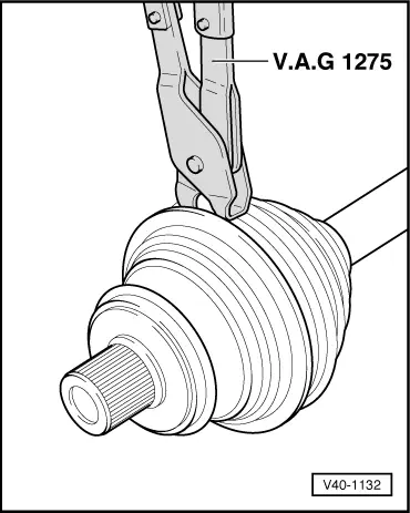
→ Fig.1    Removing and installing circlip

 
V40-0464

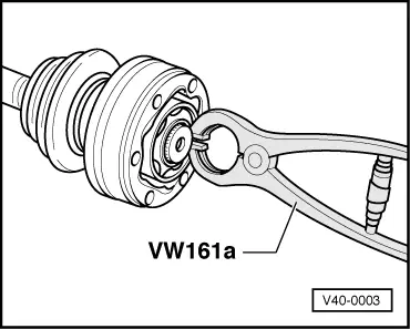
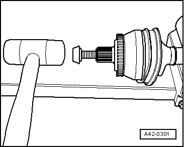
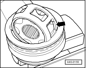
→ Fig.2    Removing outer constant velocity joint

  • ‒ Tap firmly with light alloy hammer to drive constant velocity joint off drive shaft.
 
V40-0859

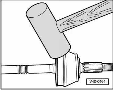
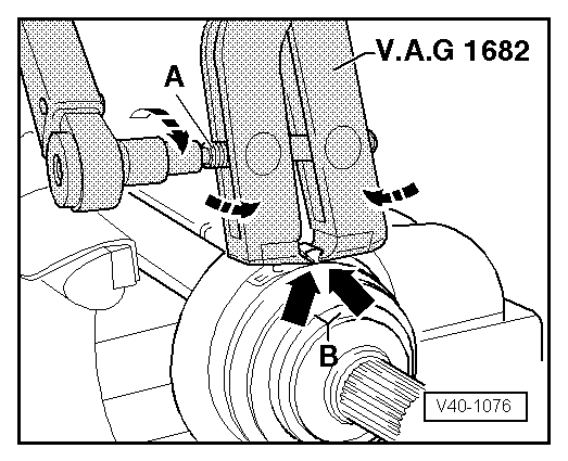
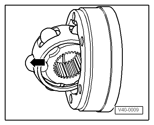
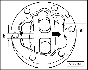
→ Fig.3     Pressing off inner constant velocity joint

  • ‒ Use mandrel to drive off boot.
  • ‒ Support ball hub when pressing off.

 
V40-0860

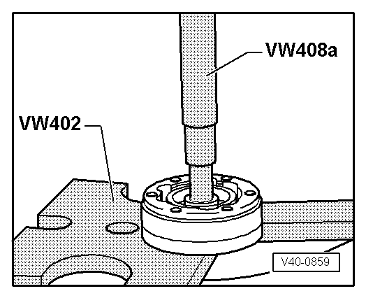
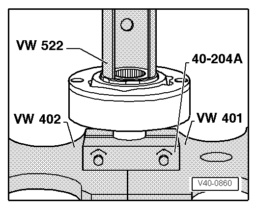
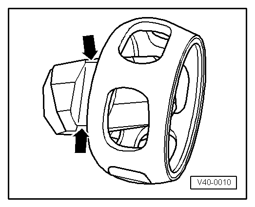
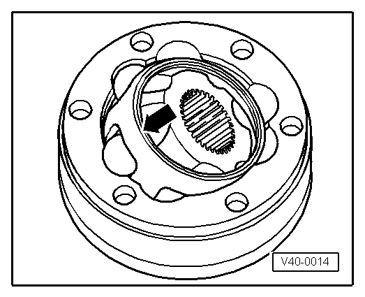
→ Fig.4    Pressing on inner constant velocity joint

  • ‒ Press on joint as far as it will go.
  • ‒ Fit circlip.

Note:

Chamfer at ID of ball hub (splines) must face contact collar of drive shaft.

 
A42-0301

→ Fig.5    Fitting outer constant velocity joint with collared bolt

  • ‒ Screw old collared bolt into joint element as shown.
  • ‒ Use plastic-headed hammer to drive joint onto shaft until circlip engages.

 
A42-0277

→ Fig.6    Coating sealing surface of cap with D 454 300 A2

  • ‒ Apply sealant -hatched area- to clean surface of cap.
    • ‒ Sealant bead: Continuous, ø2...3 mm; route round inside of holes -arrow-
  • ‒ Align cap with bolt holes and drive/press onto joint.
  • ‒ Wipe off surplus sealant.
 
A40-0157

→ Fig.7    Installation position of spacer ring and dished washer at outer joint

  •     1 -    Dished washer
  •     2 -    Spacer ring (plastic)

 
V40-0837

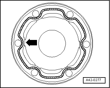
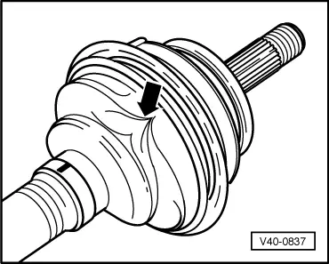
→ Fig.8    Venting rubber boot

Boot is often squashed on positioning it on joint housing. This produces a vacuum in the boot, which causes a fold to form whilst driving -arrow-.

Attention is therefore to be paid to the following:

  • ‒ Before tensioning clamps, lift boot to ensure pressure equalisation.
 
V40-1076

→ Fig.9    Tensioning stainless-steel clamps for Hytrel boots

  • ‒ Apply pliers V. A.G 1682 as shown. Make sure jaws of pliers make contact with corners (arrows B) of hose clamp.
  • ‒ Tension hose clamp by turning spindle -A- with torque wrench (take care not to tilt pliers).
    • ‒ Tightening torque: 20 Nm

Notes:

  • ◆ Make sure thread of spindle on pliers moves freely. Lubricate with MoS2 grease if necessary.
  • ◆ If stiff, e.g. due to dirt on thread, required clamp tensioning force will not be attained with specified tightening torque.
 
V40-1132

→ Fig.10    Tensioning clamp for rubber boot

 
A40-0172

Checking outer constant velocity joint

The joint must be dismantled for replacing grease in the event of severe contamination or if ball contact surfaces are to be checked for wear and damage.

Removing

  • ‒ → Use electric scriber or whetstone to mark position of ball hub with respect to ball cage and housing before dismantling -arrow-.
  • ‒ Swivel ball hub and ball cage and take out balls one after the other.

 
A40-0155
  • ‒ → Turn cage until two cage openings (arrow) are in contact with joint housing.
  • ‒ Lift out cage with hub.
 
A40-0156
  • ‒ → Swivel one hub segment into cage opening.
  • ‒ Tip hub out of cage.

Notes:

  • ◆ The 6 balls for each joint are of one tolerance group. Check stub axle, hub, cage and balls for pitting and signs of seizure.
  • ◆ Excessive backlash in joint becomes apparent from load change jolts; joint is then to be replaced.
  • ◆ Smooth areas and running marks on balls do not necessitate joint replacement.

Installing

Install in reverse order, paying attention to the following:

  • ‒ Press half the total quantity of grease into the joint housing.
  • ‒ Insert cage with hub in joint housing.

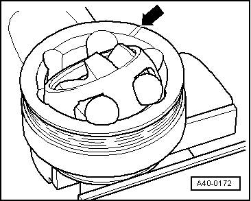
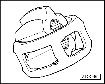
Note:

Cage must be inserted in correct position.

  • ‒ Consecutively press in opposite balls, taking care to re-establish previous position of ball hub with respect to ball cage and joint housing.
  • ‒ Insert new circlip in shaft.
  • ‒ Distribute remaining grease in boot.

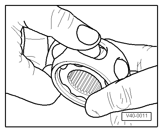
Checking inner constant velocity joint

The joint must be dismantled for replacing grease in the event of severe contamination or if ball contact surfaces are to be checked for wear and damage.

Note:

Ball hub and joint element are paired. Mark respective positions with a waterproof felt-tip pen prior to removal.
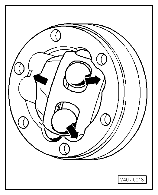
 
V40-0009

Removing

  • ‒ → Swivel ball hub and ball cage.
  • ‒ Press out joint element in direction of arrow.
  • ‒ Press balls out of cage.
 
V40-0010
  • ‒ → Tip ball hub out of ball cage via ball raceway -arrows-.
  • ‒ Check joint element, ball hub, ball cage and balls for pitting and signs of seizure.

Note:

Excessive backlash in joint becomes apparent from load change jolts. Joint is then to be replaced. Smooth areas and running marks on balls do not necessitate joint replacement.

 
V40-0011

Installing

Install in reverse order, paying attention to the following:

  • ‒ → Insert ball hub in ball cage via the two chamfers. Installation position is arbitrary. Press balls into cage.
  • ‒ Insert hub with cage and balls in upright position in joint element.
 
A40-0154

Notes:

  • ◆ → On insertion, make sure that broad gap -a- at joint element coincides with narrow gap -b- at hub after swivelling in.
  • ◆ Chamfer at ID of ball hub (splines) must face large diameter of joint element.
  • ◆ On installation, also use felt-tip pen mark made on removal as a guide.

 
V40-0013
  • ‒ → Swivel in ball hub; to do so swivel hub out of cage (arrows) until the spacing of the balls corresponds to that of the raceways.
 
V40-0014
  • ‒ → Swivel in hub with balls by pressing firmly on cage (arrow).

Checking operation of constant velocity joint

Constant velocity joint has been correctly assembled if ball hub can be pushed back and forth by hand over entire length compensation range.

Servicing drive shaft with triple roller joint AAR 2000 > < Removing and installing drive shafts