
A3 Mk1
|
Cruise control system (CCS) self-diagnosis
Checking cruise control system (CCS) - diesel engines
Requirements:
Attention:
Heed safety precautions => Page 01-1. |
 |
|
|
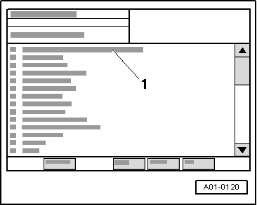
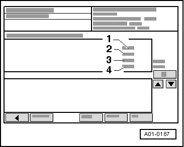
Sequence of operations → Display on VAS 5051:
|
 |
|
|
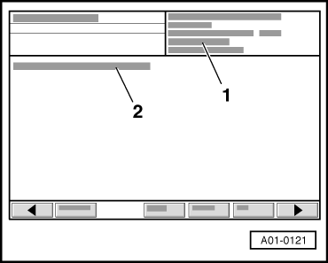
→ Display on VAS 5051:
|
 |
|
|
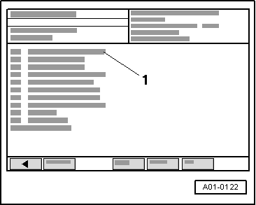
→ Display on VAS 5051:
|
 |
|
|
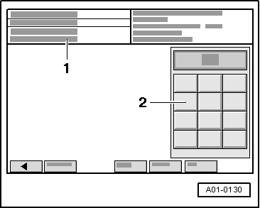
→ Display on VAS 5051:
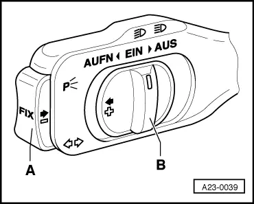
Note: On vehicles with automatic gearbox, cruise control system switch is only supplied with power at speeds in excess of 30 km/h and with selector lever set to 2, 3 or D. Power supply is then maintained even at idle, provided that gear (other than 1 or R) is engaged.
|
 |
|||||||
|
→ Display on VAS 5051:
1) If 255 is displayed: Activate cruise control system |
 |
|||||||||||||||||||||||||||||||||||||||||||||||||||||||||
If readings do not match specifications:
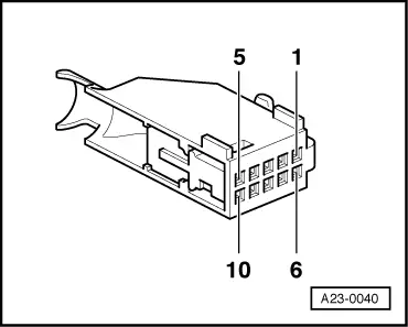
Checking wiring
=> General Body Repairs, Interior; Repair Group 70; Dash Panel
=> Injection and Glow Plug System; Repair Group 23 Notes:
Attention:
So as not to destroy electronic components, select required measuring range before connecting test leads and observe test conditions. | |||||||||||||||||||||||||||||||||||||||||||||||||||||||||
 |
|||||||||||||||
|