Audi Workshop Service and Repair Manuals
HOME
FEATURES
MENU
INDEX
ABOUT US
"concert” radio system >
< "chorus” radio system
A3 Mk1
Vehicle electrics
Radio, telephone and navigation system / Infotainment / Radio system / ock_diagram_of_radio_systems_(as_of_my_98)/">Block diagram of radio systems (as of MY 98)
Contact assignment of multi-pin connectors I, II, III, IV
Contact assignment of multi-pin connectors I, II, III, IV
Contact assignment of multi-pin connectors I, II, III, IV
Note!
Contacts not listed are not used.
20-pin connector I
1 -
Rear left signal
2 -
Rear right signal
3 -
Signal earth
6 -
Switched positive (amplifier with bass loudspeaker)
7 -
CAN bus High (infotainment) (as of MY 02)
8 -
Clock signal (up to MY 01)
9 -
Data signal (up to MY 01)
10 -
Enable signal (up to MY 01)
12 -
CAN bus Low (infotainment) (as of MY 02)
Brown 8-pin connector II
3 -
Front right loudspeaker (+)
4 -
Front right loudspeaker (-)
5 -
Front left loudspeaker (+)
6 -
Front left loudspeaker (-)
Black 8-pin connector III
1 -
GALA (vehicle-speed signal) (up to MY 01)
2 -
Anti-theft alarm earth (as of MY 02)
3 -
K-wire (diagnosis)
4 -
S-contact (terminal 86s) (up to MY 01)
6 -
Switch illumination (terminal 58s) (up to MY 01)
7 -
Battery + (terminal 30)
8 -
Earth (terminal 31)
Red 10-pin connector IV
1 -
AF mute (from telephone)
2 -
Terminal 15 (navigation system only) (up to MY 01)
3 -
Telephone (AF +) (not with navigation system)
4 -
Telephone (AF -) (not with navigation system)
5 -
Navigation (AF+) (navigation system only)
6 -
Navigation (AF-) (navigation system only)
7 -
Navigation system (control wire)
9 -
Display illumination (terminal 58d) (up to MY 01)
Vehicle electrics
Radio, telephone and navigation system / Infotainment / Radio system / ock_diagram_of_radio_systems_(as_of_my_98)/">Block diagram of radio systems (as of MY 98)
Contact assignment of multi-pin connectors I, II, III, IV
"concert” radio system >
< "chorus” radio system
 Note!
Note!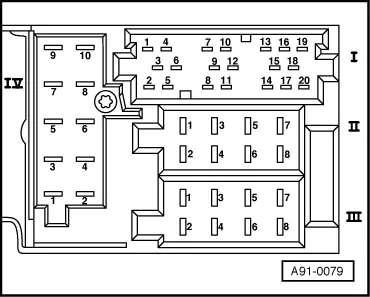
 Note!
Note!