| –
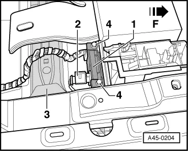
| Remove ESP sensor unit -1- upwards. |
| –
| Item -3-: seat cross member |
| Arrow in illustration faces direction of travel |

Note | t
| The ESP sensor unit is sensitive to impact. |
| t
| If the ESP sensor unit has been dropped, it may not work properly. The sensor unit is then no longer to be used. |
| Installation is performed in reverse sequence; note the following: |
| –
| Calibrate lateral acceleration sender -G200-. |
| –
| Calibrate longitudinal acceleration sender -G251- (four-wheel drive vehicles only). |
| To do so, use the vehicle diagnosis, testing and information system -VAS 5051 x- or -VAS 5052-. |
| –
| Brake system (Repair group 01; 45) |
| –
| 01 - Self-diagnosis compatible systems |
| –
| 03 - Brake electronics ABS/ESP Mark 60 |
| –
| Calibrate lateral acceleration sender -G200-. |
| –
| Calibrate longitudinal acceleration sender -G251- (four-wheel drive vehicles only), or |
| –
| Carry out ESP road test and system test. |
| To do so, use the vehicle diagnosis, testing and information system -VAS 5051 x- or -VAS 5052-. |
| –
| Brake system (Repair group 01; 45) |
| –
| 01 - Self-diagnosis compatible systems |
| –
| 03 - Brake electronics ABS/ESP Mark 60 |
| –
| J104 - Control unit for ABS/TCS/ESP, Functions |
|
|
|
