audi Workshop Repair Guides

Audi Workshop Service and Repair Manuals

Vehicles with diesel particulate filter: Control unit and hydraulic unit > < Exploded view
Removing and installing ABS control unit -J104- and ABS hydraulic unit -N55-
  Caution
ABS control unit -J104- and ABS hydraulic unit -N55- must not be separated.
Removing hydraulic unit with control unit
–  Read out control unit version and note down.
–  Disconnect battery → Electrical system; Rep. gr.27 (note radio code).
   
–  Insert brake pedal actuator -V.A.G 1869/2- between brake pedal and driver's seat (depress brake pedal at least 60 mm).
–  Connect hose of bleeder bottle to bleeder screws of front left and rear left brake calipers.
–  Open bleeder screws of rear left and front left brake calipers to release pressure in hydraulic unit.
–  Close bleeder screws of front left and rear left brake calipers.
–  Do not remove brake pedal actuator -V.A.G 1869/2-.
–  Lower vehicle.
–  Using suitable pliers, unfasten clamp at air hose to air duct and detach hose.
–  Using suitable pliers, unfasten clamps of air duct and detach.
–  Remove air duct to turbocharger from bracket.
–  Take air duct out of vehicle.
–  Unclip coolant line to coolant expansion tank from bulkhead.
–  Carefully press coolant line to one side.
  A44-0020
–  Release connector at control unit -arrow 1- and unplug -arrow 2-.
  Note
t  Make sure brake fluid does not get into connector housing of control unit. This can result in corrosion of the contacts and failure of the system.
t  Use compressed air to carefully clean connector housing if necessary.
–  Unfasten cable tie for electrical wiring to connector and move wiring clear to one side.
–  To protect against escaping brake fluid, place a sufficient number of lint-free cloths in area beneath control unit and hydraulic unit.
–  Mark brake lines.
  WARNING
Do not bend or kink brake lines.
  A45-0193
–  Unscrew brake lines from hydraulic unit -2- to brake master cylinder and tie in place.
–  Disconnect remaining brake lines -3- on hydraulic unit.
–  Seal brake lines and threaded holes using sealing plugs from repair kit.
  Note
The hydraulic pump must not be separated from the hydraulic unit.
  A45-10080
–  Carefully pull hydraulic unit -2- together with control unit and bracket -4- out of rubber buffers on mounting bracket -6-.
–  Take hydraulic unit out of vehicle.
–  Unscrew bolts -5- from bracket -4- and detach bracket.
–  Place hydraulic unit on a clean flat surface with control unit facing downwards.
  WARNING
Severe shocks or jolts can damage the control unit. The control unit must not be re-installed if it has been damaged in any way.
Seal threaded holes and brake lines using sealing plugs - 1H0.698.311.A after removing control unit and hydraulic unit.
  WARNING
Hydraulic pump must not be separated from hydraulic unit.
Installing
Installation is performed in reverse sequence; note the following:
  Note
t  The hydraulic unit supplied as a replacement is filled with brake fluid.
t  If sealing plugs are removed before fitting corresponding brake line, brake fluid will escape. Proper bleeding is then no longer ensured.
  A45-10079
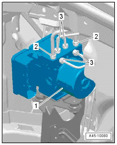
–  Secure bracket -4- by tightening bolts -5- to 8 Nm.
–  Carefully insert hydraulic unit -2- together with control unit and bracket -4- in rubber buffers on mounting bracket -6-.
Make sure that rubber buffers are not pressed through mounting bracket when inserting unit.
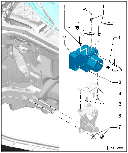
–  Connect brake lines as previously marked.
  WARNING
Interchanging brake line connections will result in ESP system malfunction.
–  Connect brake lines to hydraulic unit.
–  Attach connector to control unit and lock connector.
–  Secure electrical wiring for connector to body using a cable tie.
–  Clip coolant line to coolant expansion tank into retainers in bulkhead.
  Note
Fasten retainers at bulkhead.
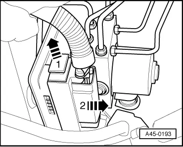
–  Insert air duct for turbocharger and use suitable pliers to fasten clamps.
–  Secure air duct for turbocharger at bracket.
–  Connect air hose and use suitable pliers to fasten clamp.
–  Bleed brake system → Chapter.
–  Perform final control diagnosis after securing brake lines to hydraulic unit.
To do this, use vehicle diagnosis, testing and information system -VAS 505x-.
  Note
Final control diagnosis can be used to establish whether line connections have been interchanged.
If a new ABS control unit -J104- has been fitted, it must be encoded.
To do this, use vehicle diagnosis, testing and information system -VAS 505x-.
–  Select on the display:
t  Running gear
t  Brake system (Repair group 01; 45)
–  Select required function on the display.
Also calibrate the following senders after renewing control unit -J104-.
t  Steering angle sender -G85-
t  Lateral acceleration sender -G200-
t  Brake pressure sender 1 -G201-
t  Longitudinal acceleration sender -G251- (only on four-wheel drive vehicles)
To do this, use vehicle diagnosis, testing and information system -VAS 505x-.
–  Select on the display:
t  Running gear
t  Brake system
t  01 - Self-diagnosis compatible systems
t  03 - Brake electronics ABS/ESP Mark 60
–  Select required function on the display.
–  Then carry out ESP road test and system test.
  WARNING
Before driving vehicle for the first time, make sure function of brakes is OK.
  A45-10079

Vehicles with diesel particulate filter: Control unit and hydraulic unit > < Exploded view