
A3 Mk2
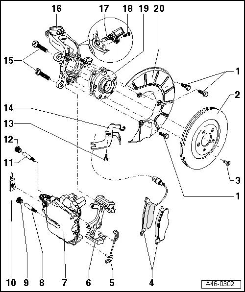
| 1 - | Bolt, 10 Nm |
| 2 - | Brake disc |
| q | Allocation, dimensions and wear limit → Chapter |
| q | To remove, unbolt brake caliper housing |
| q | Do not force brake discs off wheel hub; if necessary, use rust remover, otherwise brake discs could be damaged. |
| q | Always renew on both sides of axle |
| 3 - | Cross-head bolt, 4 Nm |
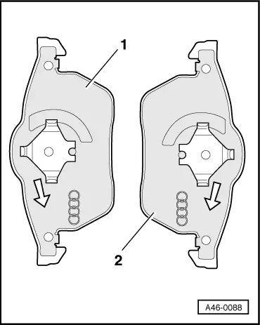
| 4 - | Brake pads |
| q | Pad thickness, wear limit → Chapter |
| q | Different versions → Parts catalogue |
| q | Checking pad thickness → Booklet808 |
| q | Removing and installing → Chapter |
| q | Note installation position → Fig. |
| q | Always renew on both sides of axle |
| 5 - | Retaining spring |
| q | Insert in both holes in brake caliper housing |
| 6 - | Brake carrier |
| q | Replacement carriers are supplied assembled and with sufficient grease on guide pins |
| q | Renew protective caps if they have been damaged (repair kit); use grease sachet supplied to lubricate the guide pins |
| 7 - | Brake caliper |
| q | Piston diameter → Chapter; different versions available → ETKA |
| q | Unscrew from brake carrier to renew brake pads |
| q | Removing and installing → Chapter |
| q | Servicing → Chapter |
| q | Brake caliper with vibration damper → Chapter |
| 8 - | Guide pin, 30 Nm |
| 9 - | Protective cap |
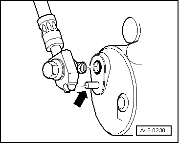
| 10 - | Brake hose with banjo union and banjo bolt, 35 Nm |
| q | Locating pin → Fig. |
| 11 - | Guide pin, 30 Nm |
| 12 - | Protective cap |
| 13 - | Self-tapping screw |
| 14 - | Bracket |
| 15 - | Ribbed bolt, 190 Nm |
| q | Clean ribs if using again |
| 16 - | Wheel bearing housing |
| 17 - | Speed sensor |
| q | Removing and installing → Chapter |
| q | Before inserting sensor, clean inner surface of fitting hole and coat with high-temperature paste -G 052 112 A3- |
| 18 - | Hexagon socket head bolt |
| q | Tightening torque → Item |
| 19 - | Wheel bearing unit with integrated rotor |
| q | Removing and installing → Rep. gr.40 |
| 20 - | Splash plate |
 Note
Note
|
|
|
|