audi Workshop Repair Guides

Audi Workshop Service and Repair Manuals

Removing and installing brake servo (TFSI) > < Removing and installing brake servo (vehicles with 7-speed dual clutch gearbox)
Removing and installing brake master cylinder (TFSI)
   
Removing and installing brake master cylinder (TFSI)
Special tools and workshop equipment required
t  Hose clamps up to 25 mm diameter -3094-
t  Torque wrench -V.A.G 1331-
t  Brake filling and bleeding equipment -V.A.G 1869-
t  Upgrade kit and extraction unit -V.A.G 1869/4-
t  Brake filling and bleeding equipment -VAS 5234-
t  Sealing plug repair kit, Part No. -1H0 698 311 A-

Removing
–  Remove engine cover panel.
   
–  Unplug electrical connector -1- on air mass meter.
–  Disconnect breather hose -3-.
–  Remove cover from air cleaner housing.
–  Disconnect air duct at clamp -2-.
–  Push air duct to one side.
  A10-10369
–  Remove battery. → Rep. gr.27
  A10-1570
–  Place air cleaner housing to side.
–  Remove battery tray -arrows-.
–  Detach battery tray from air duct at front.
–  As protection against escaping brake fluid, place a sufficient number of lint-free cloths in area beneath brake master cylinder.
–  Use the brake filling and bleeding equipment -VAS 5234- or the upgrade kit and extraction unit -V.A.G 1869/4- to extract as much brake fluid as possible from brake fluid reservoir.
  A10-1572
–  Clamp off supply hose of clutch master cylinder with hose clamps up to 25 mm diameter -3094-.
–  Pull off supply hose for clutch master cylinder.
–  Detach connector for brake fluid level warning contact.
  A30-0127
–  Disconnect brake lines -3- from brake master cylinder and seal brake lines with plugs from repair kit.
–  Unscrew securing nuts -1- for brake master cylinder.
–  If fitted, remove heat shield with retaining plate.
–  Pull brake master cylinder off brake servo.
–  Unclip brake fluid reservoir at position -2- and pull off upwards.
Installing
Installation is performed in reverse sequence; note the following:
–  Renew seal between brake master cylinder and brake servo.
–  When inserting brake master cylinder, make sure that push rod is correctly positioned in brake servo.
–  Depress brake pedal slightly to facilitate insertion of brake master cylinder in pushrod.
–  Fit air duct.
  A47-0220
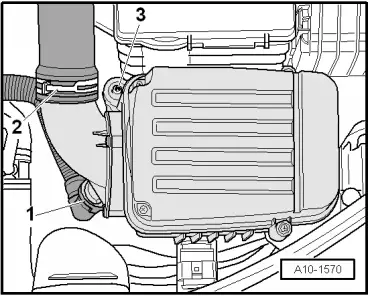
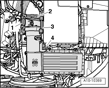
–  Connect air duct at clamp -2-.
–  Install cover on air cleaner housing.
–  Connect breather hose -3-.
–  Plug in electrical connector -1- on air mass meter.
–  Install engine cover panel.
–  Bleed brake system: ABS/ESP Mark 60 / Mark 70 → Chapter.
–  Bleed clutch hydraulics: → Rep. gr.30
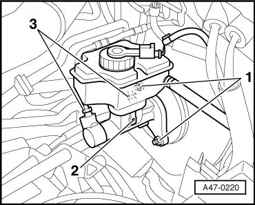
–  On vehicles with ABS/ESP, start basic setting for brake pressure sender 1 -G201-.
To do so, use the vehicle diagnosis, testing and information system -VAS 5051 x - or -VAS 5052-.
–  Carry out ESP road test and system test.
To do so, use the vehicle diagnosis, testing and information system -VAS 5051 x - or -VAS 5052-.
–  See: Running gear
–  Brake system (Repair group 01; 45)
–  01 - Self-diagnosis compatible systems
–  03 - Brake electronics ABS/ESP Mark 60
–  J104 - Control unit for ABS/TCS/ESP, Functions
Tightening torques
  A10-10369
Component Nm
Brake master cylinder to brake servo25
Brake line to brake master cylinder14
Battery tray to body 10

Renew nuts
   

Removing and installing brake servo (TFSI) > < Removing and installing brake servo (vehicles with 7-speed dual clutch gearbox)