
A3 Mk2
| Block diagram of auxiliary heater activation with remote control |
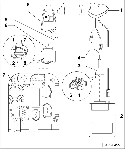
| 1 - | Roof aerial (telephone, navigation system and auxiliary heater aerial -R66-) |
| q | Designation in current flow diagram is governed by vehicle equipment → Current flow diagrams, Electrical fault finding and Fitting locations |
| q | Depending on version, vehicles with “auxiliary heater” remote control feature an additional aerial wire → Electronic parts catalogue |
| q | Removing and installing → Radio, telephone and navigation system; Rep. Gr. 91 |
| q | This aerial is used not only to receive radio signal from hand-held transmitter for remote control, but also for feed-back of reception acknowledgement to hand-held transmitter. |
| 2 - | Remote control receiver for auxiliary heater -R64- |
| q | Fitting location, removing and installing → Chapter |
| q | Transmits appropriate information to auxiliary heater control unit -J364- on reception of remote control signals (activation or deactivation of auxiliary heating/auxiliary ventilation) |
| q | Transmits reception acknowledgement back to hand-held transmitter via roof aerial. |
| q | Only remote control receiver version Telestart “T90” or “T91” should be fitted → Chapter. |
| q | The Telestart “T90” / “T91” version can be deactivated by the auxiliary heater control unit -J364- (thus reducing the no-load power input). |
| q | Checking signals from the remote control receiver for auxiliary heater -R64- → Guided Fault Finding function of vehicle diagnostic, testing and information system VAS 5051. |
 Note
Note| t | The hand-held transmitter for remote control is adapted in the remote control receiver for auxiliary heater -R64- and not in the auxiliary heater control unit -J364- → Guided Fault Finding function of vehicle diagnostic, testing and information system VAS 5051. |
| t | The signals from the hand-held transmitter for remote control are only transmitted by the remote control receiver for auxiliary heater -R64-. The signals are then processed by the auxiliary heater control unit -J364- → Guided Fault Finding function of vehicle diagnostic, testing and information system VAS 5051. |
| 3 - | 6-pin connector to remote control receiver for auxiliary heater -R64- |
| q | Contact “1”, power supply (terminal “30”) |
| q | Contact “2”, Signal wire to auxiliary heater (to auxiliary heater control unit -J364-) |
| – | Output for activation and deactivation signal to auxiliary heater control unit -J364- → Guided Fault Finding function of vehicle diagnostic, testing and information system VAS 5051 |
| – | If the receiver is in energy-saving mode, no signal is supplied after or when the ON or OFF button on the remote control is pressed → Guided Fault Finding function of vehicle diagnostic, testing and information system VAS 5051. |
| q | Contacts “3”, “4” and “5” are not used |
| q | Contact “6”, earth connection from remote control receiver for auxiliary heater -R64- |
| 4 - | Wiring to auxiliary heater control unit -J364- |
| q | Incorporated into vehicle wiring harness → Current flow diagrams, Electrical fault finding and Fitting locations |
| 5 - | Connection to vehicle wiring harness → Current flow diagrams, Electrical fault finding and Fitting locations |
| 6 - | 8-pin connector to auxiliary heater control unit -J364- |
| q | Contacts “1” and “3” to “8” → Chapter |
| q | Contact “2”, signal wire from remote control receiver for auxiliary heater -R64- |
| – | Only used on vehicles with “remote control for auxiliary heater” (optional extra) |
| – | Checking signal wire from remote control receiver for auxiliary heater -R64- (input for activation and deactivation signal in auxiliary heater control unit -J364-) → Guided Fault Finding function of vehicle diagnostic, testing and information system VAS 5051 |
| – | If the receiver is in energy-saving mode, no signal is supplied after or when the ON or OFF button on the hand-held transmitter for remote control is pressed → Guided Fault Finding function of vehicle diagnostic, testing and information system VAS 5051. |
| – | Electrical checks at connector → Guided Fault Finding function of vehicle diagnostic, testing and information system VAS 5051. |
| 7 - | Auxiliary heater control unit -J364- |
| q | Adaption of hand-held transmitter for remote control in auxiliary heater control unit -J364- → Guided Fault Finding function of vehicle diagnostic, testing and information system VAS 5051 |
| q | If auxiliary heating/auxiliary ventilation is operated by way of remote control, operating and display unit, Climatronic control unit -J255-) determines whether “auxiliary heating” or “auxiliary ventilation” mode is activated. |
| q | Adapt remote control in remote control receiver for auxiliary heater -R64-; if this component is renewed, all existing remote controls must be re-adapted one after the other → Guided Fault Finding function of vehicle diagnostic, testing and information system VAS 5051. |
Note| t | Currently a maximum of 3 remote controls can be adapted in the remote control receiver for auxiliary heater -R64-. If a fourth remote control is adapted, the first matched remote control is deleted. |
| t | The signals from the hand-held transmitter for remote control are only transmitted by the remote control receiver for auxiliary heater -R64-. The signals are then processed by the auxiliary heater control unit -J364- → Guided Fault Finding function of vehicle diagnostic, testing and information system VAS 5051. |
| t | The remote control receiver for auxiliary heater -R64- can be deactivated by the auxiliary heater control unit -J364- (thus reducing the no-load current input) → Guided Fault Finding function of vehicle diagnostic, testing and information system VAS 5051. |
| t | Checking signals from the remote control receiver for auxiliary heater -R64- → Guided Fault Finding function of vehicle diagnostic, testing and information system VAS 5051. |
| 8 - | Hand-held transmitter for remote control |
| q | For activating and deactivating “auxiliary heating” or “auxiliary ventilation” function of auxiliary heater → Chapter |
| q | When the buttons are pressed, the integrated indicator lamp lights up or flashes (green or red) → Owner's Manual. |
| q | Replacing batteries → Chapter |
| q | Corresponding button must be pressed for at least 3 seconds to enable remote control to detect pressing of buttons and transmit a radio signal → Owner's Manual |
| q | If auxiliary heater is renewed together with auxiliary heater control unit -J364-, check operation of at least one hand-held transmitter and re-adapt all hand-held transmitters if necessary → Guided Fault Finding function of vehicle diagnostic, testing and information system VAS 5051. |
| q | If remote control receiver for auxiliary heater -R64- is renewed, all hand-held transmitters must be re-adapted → Guided Fault Finding function of vehicle diagnostic, testing and information system VAS 5051 and → Chapter. |
| q | Different versions of hand-held transmitter for remote control of auxiliary heater are available (Telestart “T90” / “T91” and “T70”). Use only “T90” / “T91” version for Audi A3 vehicles → Chapter, → Chapter and → Electronic parts catalogue |