
A3 Mk2
 Note
Note
|
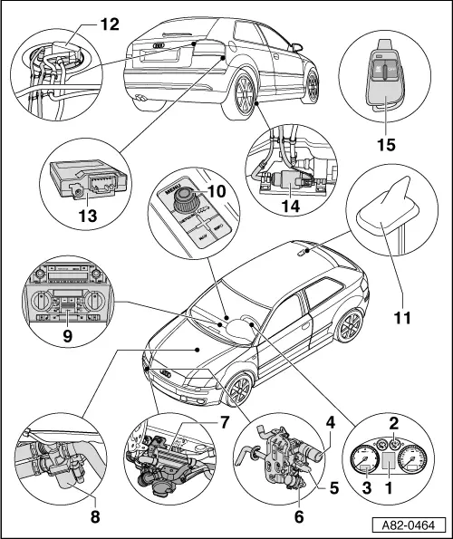
| 1 - | Driver information system (DIS) in dash panel insert |
| q | The various auxiliary heating and auxiliary ventilation activation functions are entered via the DIS and indicated on the corresponding display. |
| q | The auxiliary heater is operated via a rotary knob/pushbutton (item 10) in the centre console or the switch on the windscreen wiper lever on the steering column. The corresponding display appears on the DIS. The function is described in the owner's manual → Owner's Manual. |
| 2 - | Dash panel insert |
| q | Auxiliary heater is activated by control unit in dash panel insert -J285-. |
| q | Depending on the version, the “auxiliary heater” (optional extra) must have been adapted via the “Adaption” function in the control unit in dash panel insert -J285- → Electrical system; Rep. Gr. 01 and → Guided Fault Finding function of vehicle diagnostic, testing and information system VAS 5051. |
| q | If there is not enough fuel in the fuel tank (fuel gauge in red zone), the auxiliary heater cannot be switched on (“Auxiliary heater on immediately” function ticked in DIS and symbol for auxiliary heater mode in clock → Item cannot be activated or goes out again) → Electrical system; Rep. Gr. 01 and → Owner's Manual. |
| q | If there is a remote control for auxiliary heater (as optional extra), this activates the auxiliary heater control unit -J364-, which in turn transmits the information “Switch auxiliary heating/auxiliary ventilation on or off” via the data bus system to the control unit in dash panel insert -J285- and the Climatronic control unit -J255-. Further information → Chapter |
| 3 - | Clock |
| q | Set or activated auxiliary heating or auxiliary ventilation function is indicated by way of a symbol. |
| q | Depending on the operating status of the auxiliary heater (auxiliary heating/auxiliary ventilation mode) or if the timer function has been selected, one of the symbols for auxiliary heating/auxiliary ventilation is activated permanently, or one or both symbol(s) flash(es) → Owner's Manual. |
| 4 - | Air intake silencer |
| q | Removing and installing → Chapter |
| q | Air inlet into silencer must not be impeded (e.g. by additional fittings). |
| q | Removing intake manifold for combustion air from auxiliary heater → Chapter |
Note| t | After removing intake manifold, check relevant catch mechanisms; if retaining tabs have been broken off during removal, remove them from air intake area of auxiliary heater. |
| t | The version, layout and attachment of the air intake silencer and the intake manifold of the auxiliary heater differ on vehicles up to model year 2008 and vehicles from model year 2009 onwards (due to modified components in area of auxiliary heater); observe correct allocation → Chapter and → Electronic parts catalogue |
| 5 - | Auxiliary heater |
| q | Removing and installing → Chapter |
| q | Incorporation into coolant circuit → Chapter |
| q | Operation → Chapter |
| q | Dismantling and assembling → Chapter |
| q | Checking power supply → Guided Fault Finding function of vehicle diagnostic, testing and information system VAS 5051 |
| q | Checking electrical components of auxiliary heater → Guided Fault Finding function of vehicle diagnostic, testing and information system VAS 5051 |
| q | Block diagram of auxiliary heater → Chapter |
| q | The auxiliary heater is fitted with the following electrical components: |
| – | Combustion air blower -V6- |
| – | Glow plug with flame monitor -Q8- |
| – | Overheating fuse -S24- / overheating sensor -G189- |
| – | Temperature sensor -G18- |
| – | Auxiliary heater control unit -J364- |
| – | Fuel pre-heating heater element -Z66- (only fitted on version for vehicles with diesel engine; fuel pre-heating on auxiliary heater start-up enhances combustion particularly at low temperatures) |
| – | Fuel shut-off valve -N109- (introduction not yet finalised, currently not planned for Audi vehicles) |
Note| t | The installation of a fuel shut-off valve -N109- is currently only planned for vehicles with diesel engine (only installed on VW vehicles; introduction for Audi vehicles not yet finalised) → Electronic parts catalogue. |
| t | Currently no auxiliary heater with a fuel shut-off valve -N109- is installed in Audi A3 vehicles during production (introduction not yet finalised). However it is possible that individual vehicles have been retro-fitted with an auxiliary heater with a fuel shut-off valve -N109-; therefore it is important to pay attention to the correct version. |
| t | Auxiliary heater control unit -J364- and combustion air blower -V6- are permanently attached to auxiliary heater and currently cannot be renewed separately; dismantling and assembling auxiliary heater → Chapter. |
| t | Depending on version of auxiliary heater control unit -J364-, overheating fuse -S24- may also be referred to as overheating sensor -G189-. |
| t | When renewing, observe correct version (different versions for petrol and diesel engines) → Chapter and → Electronic parts catalogue. |
| t | If auxiliary heater is renewed together with auxiliary heater control unit -J364-, check operation of at least one hand-held transmitter for remote control and re-adapt all hand-held transmitters if necessary → Chapter and → Guided Fault Finding function of vehicle diagnostic, testing and information system VAS 5051. |
| t | When renewing, observe correct adaption for activation of fuel pump -G23- in auxiliary heating mode (fuel extraction from or next to reservoir housing of fuel tank) → Guided Fault Finding function of vehicle diagnostic, testing and information system VAS 5051. |
| t | Vehicles with diesel engine and “auxiliary heater” as an optional extra are currently also fitted with an additional electric heater → Audi Sales Programme. On vehicles with additional electric heater, the auxiliary heater is not activated as an “additional heater”. Therefore it is important to observe the adaption of the auxiliary heater control unit -J364- → Guided Fault Finding function of vehicle diagnostic, testing and information system VAS 5051. |
| t | An additional fine filter might be fitted at the fuel connection of the burner element of auxiliary heaters for vehicles with petrol engine; this filter prevents dirt particles from clogging the fuel injector tube. If there are problems with the operation of the heater, also check that this filter is not blocked (e.g. by checking fuel delivery volume with auxiliary heater switched on) → Chapter. |
| t | This auxiliary heater is available with the same part number, but with different indices for Audi and VW; when renewing auxiliary heater, observe correct index of part number → Electronic parts catalogue. If an auxiliary heater which is intended for a VW vehicle is installed in an Audi A3, the operation of the auxiliary heater can be impaired (due to different software functions) → Guided Fault Finding function of vehicle diagnostic, testing and information system VAS 5051. |
| t | From model year 2009 onwards, some components in the installation area of the auxiliary heater are modified; the modification of these parts means that certain components of the auxiliary heater, such as the air intake silencer, must also be modified. To distinguish the different versions of the auxiliary heater, the part number of the entire auxiliary heater unit (auxiliary heater with bracket, exhaust system etc.) is then changed from 1K0 xxx xxx to 8P0 xxx xxx. The auxiliary heater itself is currently not affected by this modification → Electronic parts catalogue. |
| 6 - | Circulation pump -V55- |
| q | Checking → Guided Fault Finding function of vehicle diagnostic, testing and information system VAS 5051 |
| q | Removing and installing → Chapter |
| 7 - | Silencer and exhaust pipes of auxiliary heater |
| q | Removing and installing → Chapter |
| q | Emergence of exhaust gas from exhaust pipe must not be impeded (e.g. by parking front end of vehicle over edge of pavement). |
| 8 - | Heater coolant shut-off valve -N279- |
| q | Currently, heater coolant shut-off valve -N279- is fitted on all vehicles (however, it may be discontinued on certain models in future depending on engine and vehicle equipment). |
| q | Activated in auxiliary heating mode by auxiliary heater control unit -J364- → Chapter |
| q | Removing and installing → Chapter |
| q | Checking wiring → Guided Fault Finding function of vehicle diagnostic, testing and information system VAS 5051 |
| 9 - | Air conditioner operating and display unit (Climatronic control unit -J255-) |
| q | Climatronic control unit -J255- (designation in current flow diagram and Guided Fault Finding) is activated via data bus system. |
| q | When operating auxiliary heater via “Timer” function or remote control, this determines mode in which auxiliary heater starts up (auxiliary ventilation or auxiliary heating) → Heating, air conditioning; Rep. Gr.87 and → Guided Fault Finding function of vehicle diagnostic, testing and information system VAS 5051. |
| q | With an operating and display unit, Climatronic control unit -J255- with part number 8P0 820 043 up to index Q (hardware number up to “H18” and software number up to “0260”), it may no longer be possible to change the setting on the operating and display unit under certain operating conditions following start-up of the auxiliary heater. The settings can be altered again in the usual manner after switching the ignition off and on again. If there are such problems, re-flash the software of operating and display unit (Climatronic control unit -J255-) → Guided Fault Finding function of vehicle diagnostic, testing and information system VAS 5051. |
| 10 - | Function selection switch -E91- (or -E272-) |
| q | Rotary knob/pushbutton in centre console |
| q | This function selection switch is used to enter the various auxiliary heating/auxiliary ventilation activation functions in the control unit in dash panel insert -J285-; entry is displayed in DIS. |
| q | On vehicles from model year 2005 onwards, entry in DIS is made via switch on windscreen wiper lever on steering column (gradual discontinuation of rotary knob/pushbutton in centre console) |
| 11 - | Roof aerial (telephone, navigation system and auxiliary heater aerial -R66-) |
| q | Other aerial outgoing circuits may not be used depending on version and vehicle equipment (with or without telephone/navigation system) → Radio, telephone and navigation |
| q | Different versions depending on vehicle equipment → Electronic parts catalogue |
| q | With additional aerial wire to remote control receiver for auxiliary heater -R64- → Chapter |
| 12 - | Fuel delivery unit |
| q | Different fuel delivery units depending on vehicle model (petrol or diesel engine, front-wheel drive or four-wheel drive) → Engine, mechanics; Rep. Gr. 20; Fuel supply system or → Fuel supply system; Rep. Gr. 20 |
| q | With connection to fuel extraction pipe for auxiliary heater → Engine, mechanics; Rep. Gr. 20; Fuel supply system or → Fuel supply system; Rep. Gr. 20 |
| q | Fuel extraction for auxiliary heater → Chapter |
| q | Fuel extraction pipe for auxiliary heater is gradually converted in model year 2007. Up to conversion, fuel extraction was near the reservoir housing from the fuel tank, from conversion onwards fuel extraction is from the reservoir housing. To prevent an excessive drop in the fuel level in the reservoir housing in auxiliary heating mode when the engine is not running and the fuel tank is virtually empty, on these vehicles the fuel pump -G23- is activated by the auxiliary heater control unit -J364- in auxiliary heating mode → Guided Fault Finding function of vehicle diagnostic, testing and information system VAS 5051. |
| 13 - | Remote control receiver for auxiliary heater -R64- |
| q | Fitting location, removing and installing → Chapter and → Radio, telephone, navigation |
| q | Different versions (Audi A3 may only be fitted with Telestart “T90” / “T91” version) → Chapter, → Chapter and → Electronic parts catalogue |
| 14 - | Metering pump -V54- |
| q | Removing and installing → Chapter |
| q | Fuel extraction for auxiliary heater → Chapter |
| q | Checking fuel delivery volume → Chapter |
| q | Checking activation → Guided Fault Finding function of vehicle diagnostic, testing and information system VAS 5051 |
| q | Checking wiring → Guided Fault Finding function of vehicle diagnostic, testing and information system VAS 5051 |
| q | Different versions (“DP 40” and “DP 30.4”); vehicles with petrol engine are only to be fitted with “DP 40” version; introduction of “DP 30.4” for vehicles with a diesel engine not yet finalised → Electronic parts catalogue (vehicles with a petrol engine are not to be fitted with this version) |
Note| t | Observe correct assignment of metering pump -V54- to auxiliary heater. Depending for example on the auxiliary heater version (with or without fuel shut-off valve -N109-), vehicles with a diesel engine have to be fitted with different types of metering pump -V54- → Chapter and → Electronic parts catalogue. |
| t | The installation of a fuel shut-off valve -N109- is currently only planned for vehicles with diesel engine (only installed on VW vehicles; introduction for Audi vehicles not yet finalised) → Electronic parts catalogue |
| t | Currently no auxiliary heater with a fuel shut-off valve -N109- is installed in Audi A3 vehicles during production (introduction not yet finalised). However it is possible that individual vehicles have been retro-fitted with an auxiliary heater with a fuel shut-off valve -N109-; therefore it is important to pay attention to the correct version. |
| 15 - | Hand-held transmitter for remote control |
| q | For activating and deactivating “auxiliary heating” or “auxiliary ventilation” function of auxiliary heater → Chapter |
| q | When the buttons are pressed, the integrated indicator lamp lights up or flashes (green or red) → Owner's Manual. |
| q | Replacing batteries → Chapter |
| q | Corresponding button must be pressed for at least 3 seconds to enable remote control to detect pressing of buttons and transmit a radio signal → Owner's Manual |
| q | If auxiliary heater is renewed together with auxiliary heater control unit -J364-, check operation of at least one hand-held transmitter and re-adapt all hand-held transmitters if necessary → Chapter and → Guided Fault Finding function of vehicle diagnostic, testing and information system VAS 5051. |
| q | If remote control receiver for auxiliary heater -R64- is renewed, all hand-held transmitters must be re-adapted → Guided Fault Finding function of vehicle diagnostic, testing and information system VAS 5051 and → Chapter. |
| q | Different versions of hand-held transmitter for remote control of auxiliary heater are available (Telestart “T90” / “T91” and “T70”). Use only “T90” / “T91” version for Audi A3 → Chapter, → Chapter and → Electronic parts catalogue |