audi Workshop Repair Guides

Audi Workshop Service and Repair Manuals

Removing and installing defroster flap control motorV107 > < Removing and installing fresh air blower control unitJ126
Removing and installing air flow flap control motorV71 with potentiometer for air flow flap control motorG113
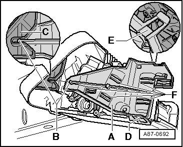
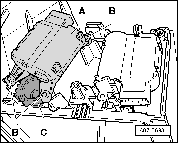
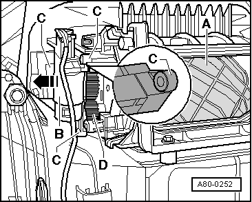
Removing and installing air flow flap control motor -V71- with potentiometer for air flow flap control motor -G113-
Vehicles with automatically controlled air conditioner
  Note
t  The air flow flap control motor -V71- is being gradually discontinued at the end of Model Year 2007. On vehicles with no air flow flap control motor -V71-, the air flow flap (fresh-air flap) is actuated by way of a cam plate and lever by the air recirculation flap control motor -V113- → Chapter. Attention is therefore to be paid to correct assignment of the operating and display unit, Climatronic control unit -J255-. If the assignment or adaption is not OK, this is detected during basic setting and stored as a fault → "Guided fault-finding" function of vehicle diagnostic, testing and information system VAS 5051 and → Electronic parts catalogue.
t  Not fitted on vehicles with manually controlled air conditioner. Vehicles with manually controlled air conditioner have no air flow flap.
t  Operation of the control motor can be checked as follows for example: Connect the two contacts „5“ and „6“ in the control motor connector to a 12 V DC source. The control motor moves as far as the stop in one direction. Interchanging positive and negative reverses the direction. Use an adapter lead for this purpose → Chapter.
t  After fitting a new control motor, perform air conditioner basic setting → "Guided fault-finding" function of vehicle diagnostic, testing and information system VAS 5051.
t  If applicable, the guided fault-finding can be used to additionally check the actuation of electrical air conditioner components e.g. by way of the interchange test → "Guided fault-finding" function of vehicle diagnostic, testing and information system VAS 5051.
t  After installing a new control motor, check actuation by the operating and display unit, Climatronic control unit -J255- and operation of the control motor (correct position of the air flow flap for air recirculation and fresh air mode) → "Guided fault-finding" function of vehicle diagnostic, testing and information system VAS 5051.
t  The air flow flap control motor -V71- can only be readily removed in the „fresh air mode stop“ position and can only be installed in this position. If the control motor comes to a halt in a different position and it can no longer be moved electrically into the „fresh air mode stop“ position, it is difficult to detach and thus remove.
Removing
–  Remove the glove compartment → General body repairs, interior; Rep. gr.68.
–  Switch on the ignition if necessary. On the operating and display unit, Climatronic control unit -J255- select „Defrost“ mode (control motor is always set to fresh-air position in this mode) and wait until the control motor has reached its „fresh air mode“ end position.
–  Switch off ignition.
   
–  Release the catches -D- and -E- for the holder -A- at the intake housing and detach the holder -A-.
–  Remove the air recirculation flap control motor -V113- → Chapter.
–  Mark the connector to the air recirculation flap control motor -V113- (to prevent interchange with the connector to the air flow flap control motor -V71-).
  A87-0692
–  Detach the control motor -A- from the intake housing.
  Note
t  The connection between the gear wheels of the control motor and the air flow flap is designed such that the control motor can only be readily detached in the „fresh air mode“ position.
t  If the control motor is in a different position and can no longer be moved, it is not possible to simply detach the control motor, but rather it must first be forced out of the mounting points -B-. Take care not to damage the gear wheel -C- when doing so.
Installing
  Note
  A87-0693
t  Replacement control motors are supplied in „fresh air mode“ position. The motor can only be attached to the gear wheel of the air flow flap when the gear wheel -A- is on stop -B-. Control motors which have been removed in a different position or actuated following removal cannot be installed.
t  If the gear wheel -A- of the control motor is not on the stop -B-„fresh air mode“, use an adapter cable → Chapter or a test lead from the adapter set -V.A.G 1594 C- for example to connect contacts 5 and 6 of the control motor via a 5 A fuse to a 12 V battery.
–  The control motor then moves in one direction as far as the stop. Interchanging positive and negative reverses the direction.
–  Actuate the control motor until the gear wheel -A- is on the „fresh air mode“ stop -B- (see Fig.).
  A87-0694
–  Before fitting the control motor, check the mounting of the air flow flap in the intake housing and of the gear wheel -C- (air flow flap open, fresh air mode).
–  Switch off ignition.
–  Connect the air flow flap control motor -V71- to the vehicle wiring harness (pay attention to correct pin assignment).
  A87-0693
–  Open the air recirculation flap -E-.
–  Reach into the intake opening for air recirculation mode and move the air flow flap -A- to the „fresh air mode“ position (intake opening for air recirculation mode closed).
  A80-0254
–  Insert the control motor -B- in the direction opposite to the arrow in the mounts -C- and position it on the gear wheel -D-.
  A80-0252
–  To enable the gear wheel at the control motor -A- to be attached to the gear wheel of the air flow flap, the short tooth -C- of the gear wheel at the control motor must coincide with the short tooth gap -D- of the gear wheel at the shaft of the air flow flap -B-.
–  Install the air recirculation flap control motor -V113- → Chapter.
–  Route the wiring harness such that it cannot come into contact with moving components (e.g. control motor lever).
  A87-0695
–  Install the holder -A-, taking particular care to ensure that the guide of the holder -B- is properly inserted in the mount of the intake housing -C- and that the holder is correctly engaged in both catches -D- and -E-.
–  Check the control motors. They must be held in position by the holder -A-. Eliminate any clearance if necessary by attaching a piece of foam to the inside of the attachment points -F- of the holder -A- .
  Note
t  The position of the air flow flap control motor -V71- and the air recirculation flap control motor -V113- (and the associated flaps) can no longer be seen with the glove compartment fitted. It is therefore appropriate to check operation before fitting the glove compartment.
t  If the two gear wheels (at the air flow flap control motor -V71- and the air flow flap) have been assembled in the wrong position, the air flow flap will not reach its two end positions (may be detected as a fault via the „Basic setting“ function) or the control motor will not run smoothly.
–  After installing the control motors, perform air conditioner basic setting and then interrogate the air conditioner event recorder → "Guided fault-finding" function of vehicle diagnostic, testing and information system VAS 5051.
–  Switch on ignition.
  A87-0692
–  Actuate the air flow flap control motor -V71- and the air recirculation flap control motor -V113- by way of the operating and display unit, Climatronic control unit -J255- until the gear wheel is on the „air recirculation mode“ stop (this illustration shows the air flow flap -A- on the „fresh air mode“ stop) and then check the position of the air flow flap (must be closed).
–  Initially select the „air recirculation mode“ function on the operating and display unit, Climatronic control unit -J255-.
  A80-0254
The air recirculation flap control motor -V113- opens the flap -E- and the air flow flap control motor -V71- moves the air flow flap -A- to the position „air intake opening for air recirculation mode open“.
Wait until both control motors have reached their end position.
–  Select the „fresh air mode“ function e.g. by way of „defrost“ mode (the control motors are always set to the „fresh air mode“ position in this mode).
The air flow flap control motor -V71- sets the air flow flap -A- to the position „air intake opening for air recirculation mode closed“. The air recirculation flap control motor -V113- moves the flap -E- to a position specified by the operating and display unit, Climatronic control unit -J255-.
Wait until both control motors have reached their end position.
Re-install the remaining components removed in reverse order.
  Note
t  With the air recirculation flap -E- closed, the position of the air flow flap -A- can be seen by way of the air intake opening in the plenum chamber (remove plenum chamber cover).
  A80-0254
t  For regulation of the air flow, the fresh air intake duct is partially closed via the air flow flap -A- at higher vehicle speeds (as of approx. 80 km/h) by the operating and display unit, Climatronic control unit -J255- (the position of the air recirculation flap -E- is specified by the operating and display unit, Climatronic control unit -J255-).
t  To reduce the change in noise of the fresh air blower -V2- caused by differences in air intake on switching from fresh-air to air recirculation mode or vice versa (switching is effected automatically for example on vehicles with air quality sensor -G238- in the event of air pollution), the air flow flap control motor -V71- and the air recirculation flap control motor -V113- are actuated as follows:
t  Switching from fresh air to air recirculation mode: The air recirculation flap -E- is opened first and the fresh-air intake duct then closed by way of the air flow flap -A-.
t  Switching from air recirculation to fresh air mode: The fresh-air intake duct is opened first by way of the air flow flap -A- and the air recirculation flap -E- then closed.
  A80-0254
t  In partial air recirculation mode, the air recirculation flap -E- is opened and the air flow flap (fresh-air flap) -A- moved to mid-position by the operating and display unit, Climatronic control unit -J255- (fresh-air and air recirculation intake ducts are simultaneously opened slightly). This ensures improved cooling in certain temperature ranges and at the same time the intake of a certain proportion of fresh air.
  A80-0254

Removing and installing defroster flap control motorV107 > < Removing and installing fresh air blower control unitJ126