
A3 Mk2
 Note
Note
|
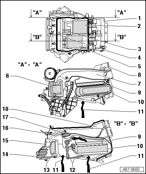
| 1 - | Air distribution housing |
| 2 - | Left temperature flap (driver side) |
| q | On vehicles with manually controlled air conditioner, the right and left temperature flaps are linked by way of the shaft and moved jointly by the temperature flap control motor -V68-. |
| q | Shown in „cooling“ position |
| 3 - | Air routing to air duct to vent in rear centre console and centre dash panel vents |
| 4 - | Air routing to air duct to vent in rear centre console and centre dash panel vents |
| 5 - | Right temperature flap (front passenger side) |
| q | On vehicles with manually controlled air conditioner, the right and left temperature flaps are linked by way of the shaft and moved jointly by the temperature flap control motor -V68-. |
| q | Shown in centre position |
| 6 - | Left footwell flap (driver side) |
| q | Shown in „closed“ position |
| q | On vehicles with automatically controlled air conditioner, the central flaps (left, right and centre) and the two footwell flaps are moved jointly by way of the cam plates attached to the control motor/shaft. |
| q | On vehicles with manually controlled air conditioner, the flaps are actuated by way of a flexible shaft and cam plate → Chapter. |
| 7 - | Air duct to left footwell (driver side) |
| 8 - | „A“-„A“ sectional view of air distribution housing |
| 9 - | Supplementary air heater element -Z35- (with supplementary air heater control unit -J604-) |
| q | Not installed in all vehicles |
| q | Only provided for vehicles with diesel engine. An electric supplementary air heater or a fuel-driven supplementary heater is fitted depending on vehicle equipment → "Guided fault-finding" function of vehicle diagnostic, testing and information system VAS 5051 (and also for the relevant engine control unit). |
| 10 - | Heating system heat exchanger |
| 11 - | Air inlet from evaporator housing |
| 12 - | Right temperature flap (front passenger side) |
| q | On vehicles with manually controlled air conditioner, the right and left temperature flaps are linked by way of the shaft and moved jointly by the temperature flap control motor -V68-. |
| q | Shown in centre position |
| 13 - | Right footwell flap (front passenger side) |
| q | Shown in „closed“ position |
| q | On vehicles with automatically controlled air conditioner, the central flaps (left, right and centre) and the two footwell flaps are moved jointly by way of the cam plates attached to the control motor/shaft. |
| q | On vehicles with manually controlled air conditioner, the flaps are actuated by way of a flexible shaft and cam plate → Chapter. |
| 14 - | Defrost flap |
| q | Shown in „closed“ position |
Note| t | On vehicles with a manually controlled air conditioner (no automatic air conditioner) the modification to this flap has no effect on air conditioner control (the flap is only actuated by way of the setting on the manual air conditioner controls) . |
| t | On vehicles with an automatically controlled air conditioner the air conditioner operating and display unit, Climatronic control unit -J255- was already modified at the end of Model Year 2007 → Electronic parts catalogue. On air conditioner operating and display units, Climatronic control unit -J255- with part number „8P0 820 043“ as of index „AE“, the „Adaption“ function can be used to enter the version of the flap in the air outlet to the dash panel defroster vents and the number of control motors at the air conditioning unit (with and without air flow flap control motor -V71-) (adaption of air conditioner operating and display unit, Climatronic control unit -J255-) → "Guided fault-finding" function of vehicle diagnostic, testing and information system VAS 5051. |
| 15 - | „B“-„B“ sectional view of air distribution housing |
| 16 - | Central flap „Centre“ |
| q | Shown in „open“ position |
| q | On vehicles with automatically controlled air conditioner, the central flaps (left, right and centre) and the two footwell flaps are moved jointly by way of the cam plates attached to the control motor/shaft. |
| q | On vehicles with manually controlled air conditioner, the flaps are actuated by way of a flexible shaft and cam plate → Chapter. |
| 17 - | Flap in air duct for air routing to vent in rear centre console |
| q | This flap is actuated via an actuating arm attached to the centre central flap. |
| 18 - | Air duct for air routing to vent in rear centre console |
| q | This duct is currently sealed with a plug. |
| q | The introduction of a vent in the rear centre console has not yet been finalised. |