audi Workshop Repair Guides

Audi Workshop Service and Repair Manuals

Measures to be taken if readout does not match specification > < Test requirements
Checking cooling output
Test requirements satisfied → Chapter.
–  Measure the ambient temperature (must be above 15 °C).
–  Close the doors, front lid, windows and sun roof.
–  Open all dash panel vents.
–  Switch on ignition.
–  Start the engine.
–  On the operating and display unit, Climatronic control unit -J255-, set „Econ“ mode (on the version with ECON button the indicator lamp in the button lights, on the version with AC button the lamp in the button does not light).
–  Start air conditioner guided fault-finding → "Guided fault-finding" function of vehicle diagnostic, testing and information system VAS 5051.
–  In the „Reading measured value block“ function, select the display group with the measured values for actuation of the air conditioner compressor and the pressure in the refrigerant circuit and read out the measured values → "Guided fault-finding" function of vehicle diagnostic, testing and information system VAS 5051.
t  The air conditioner compressor is switched off, a current of 0 A (amps) is displayed.
t  At the measured ambient temperature, the pressure in the refrigerant circuit is equal to or higher than the value in the table.
   
Ambient temperature in °CDisplayed pressure (in bar absolute)
154,7
205,6
256,6
307,6
358,8

  Note
t  At absolute pressure, 0 bar corresponds to an absolute vacuum. Normal ambient pressure thus corresponds to roughly 1 bar absolute. On the scales of most pressure gauges, 0 bar corresponds to an absolute pressure of one bar (can be seen from -1 mark below 0).
t  Depending on the version of the operating and display unit, Climatronic control unit -J255-, the measured value block may only display values as whole numbers. The display fluctuates between two values if the measured pressure is between the two.
t  
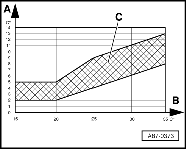
The pressure in the refrigerant circuit is governed by the ambient temperature. Due to the radiation of heat by components (e.g. the radiator), the pressure displayed with a warm engine is slightly higher than that given for the corresponding ambient temperature.
If the displayed pressure in the refrigerant circuit is lower than that given in the table:
t  Check the signal of the high-pressure sender -G65- → Chapter.
t  If no fault is found at the high-pressure sender -G65-, there is not enough refrigerant in the circuit. Take the vehicle to a workshop equipped with the necessary tools where the work can be performed by appropriately qualified personnel → Air conditioner with refrigerant R134a.
If the pressure in the refrigerant circuit is OK (equal to or greater than that given in the table)
–  Switch on the air conditioner compressor by selecting „Auto“ mode on the operating and display unit, Climatronic control unit -J255-.
–  Set „Lo“ temperature (for driver and passenger side) on the operating and display unit, Climatronic control unit -J255-.
–  Set the air outflow direction on the operating and display unit, Climatronic control unit -J255- to „dash panel vents“.
–  Read out the values required in the guided fault-finding → "Guided fault-finding" function of vehicle diagnostic, testing and information system VAS 5051.
Check the following values:
t  Air conditioner compressor switched on: Indication of a signal ratio greater than 30 % (actuation of the air conditioner compressor regulating valve -N280-).
t  Air conditioner compressor switched on: Indication of a current greater than 0.3 A (current flowing via the air conditioner compressor regulating valve -N280-).
t  The pressure displayed rises above the value with the air conditioner compressor switched off.
  Note
t  If the pressure displayed does not change and actuation of the air conditioner compressor is OK, check again as to whether the air conditioner compressor is actually being driven. If it is, there is a fault in the refrigerant circuit. The vehicle is to be taken to a workshop equipped with the necessary tools where the work can be performed by appropriately qualified personnel → Air conditioner with refrigerant R134a (there may be problems with air conditioner compressor control). Inform the workshop of the problems encountered.
t  The air conditioner compressor regulating valve -N280- is actuated by the operating and display unit, Climatronic control unit -J255- such that the temperature of the air downstream of the evaporator reaches the specified value (approx. 2 to 5 °C).
t  After starting the vehicle, a value greater than 75 % (0.55 A) is displayed for actuation of the air conditioner compressor regulating valve -N280- depending on the measured temperature, engine speed and electrical system voltage. As soon as the temperature measured by the evaporator output temperature sender -G263- approaches the specified value, actuation is cancelled and the compressor output thus reduced.
t  Under certain operating conditions, residual moisture in the refrigerant circuit may lead to the formation of ice at the air conditioner compressor regulating valve (and at the expansion valve). Such ice formation impedes air conditioner compressor control. The evaporator is excessively cooled and ices up. Icing-up of the evaporator may give rise to various problems → Chapter.
t  If no or an insufficient current is displayed in the measured value block for actuation of the air conditioner compressor regulating valve -N280-, check actuation of -N280- → Chapter.
–  Press the air recirculation mode button on the operating and display unit, Climatronic control unit -J255- (symbol for „air recirculation mode“ in button lights).
–  Set the engine speed to 2000 rpm (start of time measurement).
–  Select the „Reading measured value block“ function and then the display with the measured value of the evaporator output temperature sender -G263- → "Guided fault-finding" function of vehicle diagnostic, testing and information system VAS 5051.
   
–  Compare the measured value displayed (for -G263-) to the values in the graph → "Guided fault-finding" function of vehicle diagnostic, testing and information system VAS 5051.
A - Air temperature measured by evaporator output temperature sender -G263-
B - Ambient temperature
C - Permissible tolerance range
Depending on ambient temperature, the measured air temperature must be within the stated tolerance range after 5 minutes.
  Note
t  If the required values are not attained, check the measured value of the evaporator output temperature sender -G263-, the left vent temperature sender -G150- and the right vent temperature sender -G151- and compare the measured values displayed:
t  If the measured value in the display zones differs, perform the measures to be taken if the readout does not match the specification → Chapter.
t  If the measured value of the evaporator output temperature sender -G263- is higher than that of the left vent temperature sender -G150- and the right vent temperature sender -G151-, check proper installation of the evaporator output temperature sender -G263- and perform the electrical check for this sender → "Guided fault-finding" function of vehicle diagnostic, testing and information system VAS 5051.
t  Operation of the air conditioner can be seen, for example, from the fact that the refrigerant pipe on the low-pressure end (thick pipe) cools down.
If the measured value of the evaporator output temperature sender -G263- (and thus the system cooling output) is OK:
–  Compare the measured value displayed (for the evaporator output temperature sender -G263-) to the measured values for the left vent temperature sender -G150- and the right vent temperature sender -G151-.
After 5 minutes, the measured values for -G150- and -G151- must not be more than 3 °C higher than that for -G263-.
  Note
t  If the required values are not attained, compare the measured values displayed for the left vent temperature sender -G150- and the right vent temperature sender -G151-:
t  If the measured value in one of the two senders is OK, check actuation and operation of the left temperature flap control motor -V158- and the right temperature flap control motor -V159- → Chapter, → Chapter and → "Guided fault-finding" function of vehicle diagnostic, testing and information system VAS 5051.
t  If the measured value for the left vent temperature sender -G150- and the right vent temperature sender -G151- is lower than that for the evaporator output temperature sender -G263-: Check -G263-, -G150- and -G151- for proper installation and contact resistance in the electrical connections. Replace the defective sender if applicable → "Guided fault-finding" function of vehicle diagnostic, testing and information system VAS 5051.
t  If no fault is found at -G150- and -G151-, as well as at the left temperature flap control motor -V158- and -V159-, perform the measures to be taken in the event of temperature increase downstream of the evaporator → Chapter.
t  The temperature of the air flow from the „Centre“ dash panel vents can additionally be measured using a commercially available thermometer for example.
t  Problems relating to differences between the temperature of the air emitted from the vents with an identical setting in air conditioner control mode may be due to the following: Temperature flaps in air distribution housing not closing completely or not reaching their end position → Chapter and → "Guided fault-finding" function of vehicle diagnostic, testing and information system VAS 5051, air in heat exchanger (fluctuating flow through heat exchanger and thus uneven heat distribution) → Chapter or detachment of foam seal on installation of heat exchanger, thus allowing air to flow past the heat exchanger.
  A87-0373

Measures to be taken if readout does not match specification > < Test requirements