
A3 Mk2
|
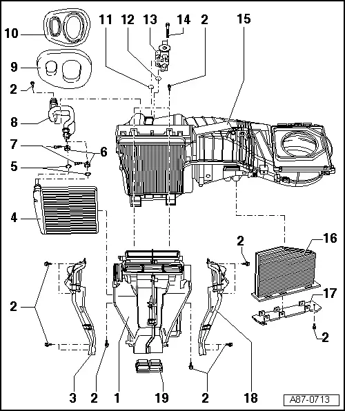
| 1 - | Air conditioner air distribution housing |
| q | Not to be further dismantled |
| q | On vehicles with no supplementary air heater element -Z35-, the opening for -Z35- is sealed with the cover for the heat exchanger. |
| q | If necessary, moisten the mounts and guides of the temperature flaps with a small quantity of grease (e.g. G 052 745 A3). |
| q | Different versions for vehicles with manually and automatically controlled air conditioner → Electronic parts catalogue |
| q | The air distribution housing for vehicles with manually controlled air conditioner is provided with a gear mechanism with cam plate for actuating the air distributor flaps. This gear mechanism is not to be detached, as the setting cannot be re-established. |
| q | Air distribution housings (for heater or air conditioner) with a flap in the air outlet to the dash panel defroster vents with no side recess were gradually introduced as of November 2007. On vehicles with no air conditioner (heater only) or with manually controlled air conditioner, the modification to this flap has no effect on control (the flap is only actuated by way of the setting on the heater/manual air conditioner controls) → Chapter. |
 Note
Note| t | On vehicles with manually controlled air conditioner, the air distribution flaps are moved manually by way of a flexible shaft. On vehicles with automatically controlled air conditioner, the air distribution flaps are actuated by different control motors. |
| t | On vehicles with manually controlled air conditioner, the temperature flaps (right and left temperature flaps) are linked by way of the shaft and actuated by a control motor. On vehicles with automatically controlled air conditioner, the left and right temperature flaps are actuated by separate control motors. |
| t | On vehicles with a manually controlled air conditioner (no automatically controlled air conditioner) the modification to this flap has no effect on air conditioner control (the flap is only actuated by way of the setting on the manual air conditioner controls) . |
| t | On vehicles with an automatically controlled air conditioner the air conditioner operating and display unit, Climatronic control unit -J255- was already modified at the end of Model Year 2007 → Electronic parts catalogue. On air conditioner operating and display units, Climatronic control unit -J255- with part number „8P0 820 043“ as of index „AE“, the „Adaption“ function can be used to enter the version of the flap in the air outlet to the dash panel defroster vents and the number of control motors at the air conditioning unit (with and without air flow flap control motor -V71-) (adaption of air conditioner operating and display unit, Climatronic control unit -J255-) → "Guided fault-finding" function of vehicle diagnostic, testing and information system VAS 5051. |
| 2 - | Bolt |
| 3 - | Air duct to left footwell vent |
| q | „Air conditioner“ version (with mount for temperature sensor) |
Note| On vehicles with manually controlled air conditioner, the temperature sensor is to be discontinued at a later date (not yet finalised). The mount is sealed on vehicles with no temperature sensor. |
| 4 - | Heating system heat exchanger |
| q | Removing and installing → Chapter |
| 5 - | Sealing ring |
| q | Replace |
| q | Moisten slightly with coolant and fit in correct position → Chapter |
| 6 - | Clamp |
| q | Replace |
| q | Ensure correct positioning. |
| q | Removing and installing → Chapter |
| 7 - | Bolt |
| q | Tightening torque 2.5 Nm |
| 8 - | Coolant pipes |
| q | Detaching from heat exchanger/attaching → Chapter |
| 9 - | Foam spacer |
| q | Fitted between grommet and air conditioning unit |
| 10 - | Grommet |
| q | Insert in vehicle bulkhead before fitting the air conditioning unit → Chapter |
| q | Installing → Chapter |
| 11 - | O-ring |
| q | Replace → Chapter |
| q | For assignment, refer to → Electronic parts catalogue |
| 12 - | O-ring |
| q | Replace → Chapter |
| q | For assignment, refer to → Electronic parts catalogue |
| 13 - | Expansion valve |
| q | Detaching and attaching refrigerant lines → Chapter |
| q | Removing and installing → Chapter. |
Note| After switching off the air conditioner compressor, a relatively long period may elapse with this vehicle before the pressure on the high-pressure end decreases (the expansion valve is cold and the pressure on the low-pressure end increases rapidly after switch-off, the expansion valve closes and the refrigerant can only flow slowly to the low-pressure end). |
| 14 - | Bolt |
| q | Tightening torque 10 Nm |
| q | Removing and installing → Chapter. |
| 15 - | Evaporator housing |
| q | Dismantling and assembling → Chapter |
| 16 - | Dust and pollen filter |
| q | Removing and installing → Chapter |
| q | Heed replacement intervals → Maintenance tables |
| q | With activated charcoal element → Chapter |
| 17 - | Dust and pollen filter cover |
| q | Removing and installing → Chapter |
| 18 - | Air duct to right footwell vent |
| q | Different versions for vehicles with manually controlled air conditioner (no mount for temperature sensor) and vehicles with automatically controlled air conditioner (with mount for temperature sensor) |
| 19 - | Sealing plug |
| q | Only fitted on vehicles with no air duct to the vent in the rear centre console (introduction of vent in centre console not yet finalised). |