| Checking pressure signal from high-pressure sender -G65- |

Note | t
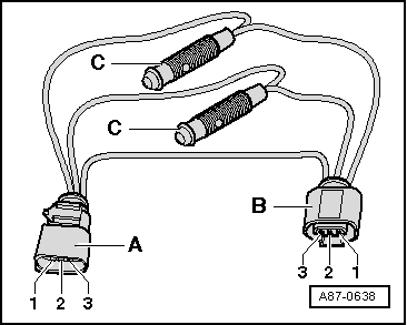
| On vehicles with automatically controlled air conditioner, the operating and display unit, Climatronic control unit -J255- evaluates the signal from the high-pressure sender -G65- and actuates the air conditioner compressor by way of the air conditioner compressor regulating valve -N280-. |
| t
| On vehicles with manually controlled air conditioner, the air conditioning system control unit -J301- evaluates the signal from the high-pressure sender -G65- and actuates the air conditioner compressor by way of the air conditioner compressor regulating valve -N280-. |
| t
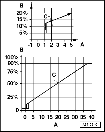
| Depending on the version of the high-pressure sender -G65-, the measured value for the pressure in the refrigerant circuit transmitted by the high-pressure sender -G65- may be too low at low ambient temperatures (ambient temperature less than 5 °C) although the air conditioner is OK and the refrigerant circuit has been properly charged. A fault entry may therefore be erroneously made at low ambient temperatures (ambient temperature less than 5 °C) in the air conditioning system control unit -J301- or with air conditioner operating and display units, Climatronic control unit -J255- with part number „8P0 820 043“ up to index „AH“ (fault memory entry: High-pressure sender -G65-„Lower limit value not reached“). If the fault is only displayed as a sporadic fault at ambient temperatures calculated by the air conditioner of above 5 °C and the air conditioner is functioning properly, the fault memory entry can be erased (no further action is necessary). |
| t
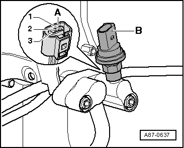
| The fitting locations differ depending on the engine. On vehicles with 2.0 l diesel engine, the high-pressure sender -G65- for example is not fitted at the refrigerant line from the expansion valve to the condenser, but rather at the refrigerant line between the air conditioner compressor and the condenser. |
| t
| On vehicles with 4-cyl. engine, the connector of the high-pressure sender -G65- can currently be unplugged without having to remove other components (accessible from above). |
| t
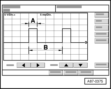
| After switching off the air conditioner compressor, a relatively long period may elapse with this vehicle before the pressure on the high-pressure end decreases (the expansion valve is cold and the pressure on the low-pressure end increases rapidly after switch-off, the expansion valve closes and the refrigerant can only flow slowly to the low-pressure end). |
|
|
|