
A3 Mk2
| Removing and installing input shaft, output shaft (pinion shaft), differential, selector mechanism and selector forks |

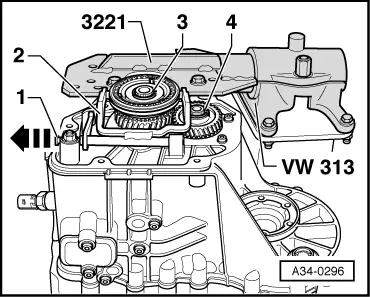
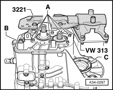
| Special tools and workshop equipment required |
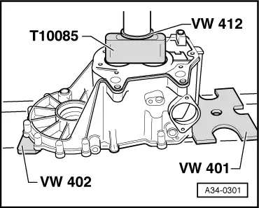
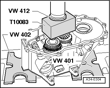
| t | Thrust plate -VW 401- |
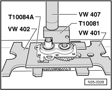
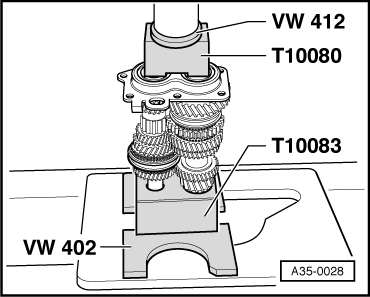
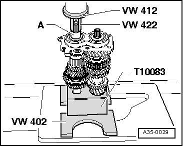
| t | Thrust plate -VW 402- |
| t | Press tool -VW 407- |
| t | Press tool -VW 412- |
| t | Tube -VW 422- |
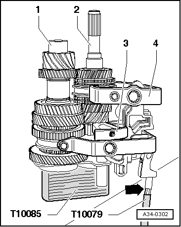
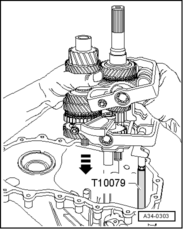
| t | Guide pin -T10079- |
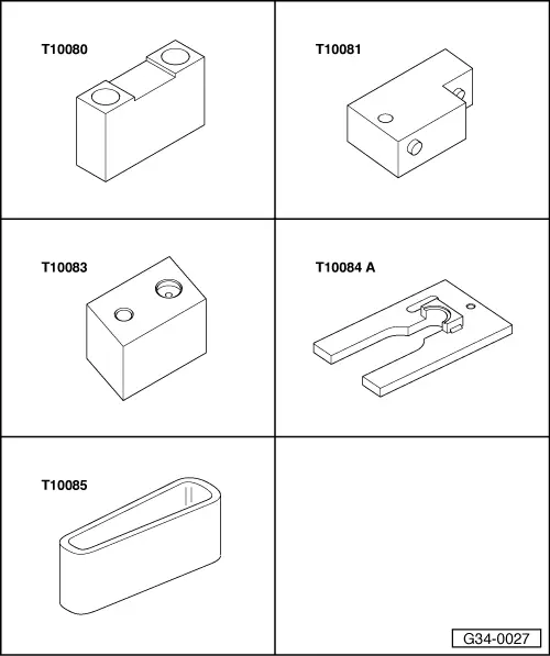
| t | Thrust piece -T10080- |
| t | Thrust piece -T10081- |
| t | Thrust block -T10083- |
| t | Thrust plate -T10084 A- |
| t | Thrust piece -T10085- |
|
|
|
|
|
|
|
|
|
|
|
|
|
|
|
|
|
|
|
|
|
|
 Note
Note
|
|
Note
|
|
Note
|
|
Note
|
|
 WARNING
|
|
|
|
|
|
|
|
|
|
|
|
Note
|
|
|
|
|
|
|
|
|
|
|
|
| Circlip thickness (mm) | ||
| 2.00 | 2.10 | 2.20 |
|
|
|