audi Workshop Repair Guides

Audi Workshop Service and Repair Manuals

Exploded view - selector lever handle, selector lever display illumination bulbL101 and selector lever position displayY26 > < There is currently no provision for repairs to the clutch.
Electrical/electronic components and fitting locations
   
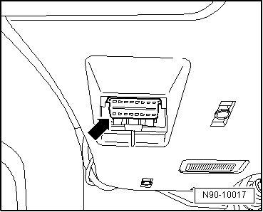
Diagnostic connection
t  Fitting location: The diagnostic connection is located below the knee padding to the left of the steering wheel.
The components listed below can be tested with the Guided Fault Finding function in the vehicle diagnostic tester.
  N90-10017
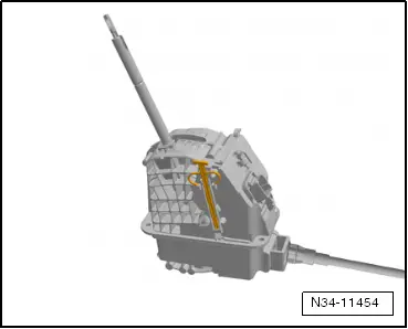
Selector lever lock solenoid -N110-
t  Fitting location: The selector lever lock solenoid -N110- is a component part of the shift unit.
  Note
If the selector lever lock solenoid -N110- is defective the entire shift unit has to be renewed → Chapter.
  N34-11454
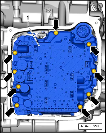
Mechatronic unit for dual clutch gearbox -J743-
t  Fitting location: The mechatronic unit for dual clutch gearbox -J743--item 1- is bolted to the front of the gearbox housing -arrows- and covered by the gearbox oil pan.
t  The control unit is an integrated component of the mechatronic unit for dual clutch gearbox -J743-.
→ Chapter „Removing and installing mechatronic unit for dual clutch gearbox -J743-“.
  N34-11658
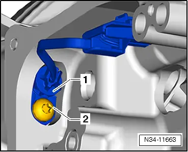
Gearbox input speed sender -G182-/clutch temperature sender -G509-
t  Fitting location: The gearbox input speed sender -G182-/clutch temperature sender -G509--1- is secured to the gearbox housing with bolt -2-.
→ Chapter „Removing and installing gearbox input speed sender -G182-/clutch temperature sender -G509-“.
  N34-11663
Selector lever sensors control unit -J587- with selector lever -E313-, tiptronic switch -F189-, selector lever locked in position P switch -F319-
t  Fitting location: The components are integrated in the printed circuit of the shift unit; they cannot be renewed separately.
  Note
The shift unit must be renewed if one of the components is defective → Chapter.
  N34-11454
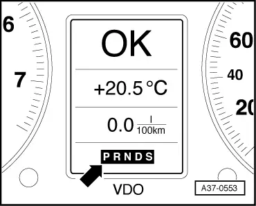
Selector lever position display -Y6-
t  Fitting location: The selector lever position display -Y6--arrow- is integrated in the instrument cluster and cannot be renewed separately.
  Note
t  If the selector lever position display flashes or lights up, please refer to safety functions of gearbox control unit → Chapter.
t  If the selector lever position display -Y6- is defective, the instrument cluster must be renewed → Electrical system; Rep. gr.90.
  A37-0553
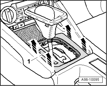
Selector lever display illumination bulb -L101- with selector lever position display -Y26-
t  Fitting location: in trim frame -1-
→ Chapter „Removing and installing selector lever display illumination bulb -L101- with selector lever position display -Y26-“.
  A96-10095
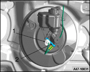
Brake light switch -F-
t  Fitting location: The brake light switch-2- is located on the brake master cylinder.
Removing and installing brake light switch → Brake system; Rep. gr.45.
  A47-10031
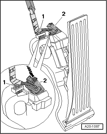
Kick-down switch -F8-
An adapted value from accelerator position sender -G79-/accelerator position sender 2 -G185- (integrated in accelerator pedal module) is stored in the engine control unit as the kickdown signal. The accelerator position senders cannot be renewed separately.
t  Signal is transmitted from engine control unit to gearbox control unit via CAN bus.
  Note
The accelerator pedal module must be renewed if one of the accelerator position senders is defective → Fuel supply system, petrol engines; Rep. gr.20.
  A20-1087

Exploded view - selector lever handle, selector lever display illumination bulbL101 and selector lever position displayY26 > < There is currently no provision for repairs to the clutch.