audi Workshop Repair Guides

Audi Workshop Service and Repair Manuals

Gearbox mechanics,operation, construction,diff. > < Exploded view - multiple clutch
Removing and installing multiple clutch
Special tools and workshop equipment required
   
t  Assembly sleeve -T10302-
  W00-10302
t  Retaining pin -T10303-
  Note
Assembly sleeve -T10302- must be cleaned before use; do not use an assembly sleeve if it is scratched.
  W00-10303
Removing clutch end cover
–  Drain gear oil → Chapter.
–  Remove gearbox → Chapter.
–  Secure gearbox to engine and gearbox support in vertical position → Chapter.
–  Renew gear oil filter → Chapter.
  N34-10517
–  Using a screwdriver -1-, pry out circlip -2- for clutch end cover -arrow- and take out circlip.
  A30-10057
–  Working through opening for starter motor, pry off clutch end cover -2- using a screwdriver -1- or suitable lever -arrow- and take off clutch end cover.
  A30-10058
Removing multiple clutch
–  Pry out circlip -2- using a screwdriver -1--arrow-.
  A30-10059
–  Remove drive plate -arrows-.
  N30-10094
–  Use screwdriver or suitable pliers to pry out circlip -arrow-.
  Note
This circlip must be replaced with a new circlip of the correct thickness when re-assembling.
  N30-10095
–  Take out multiple clutch.
–  After removing multiple clutch, check clutch bellhousing for damage caused during removal.
  N30-10089
–  Pull out pump shaft -A-.
  Note
The pump shaft is not re-installed until after the new clutch has been fitted. Keep the shaft in a suitable place until it is required.
  N30-10088
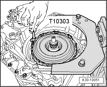
Installing multiple clutch
  Caution
t  
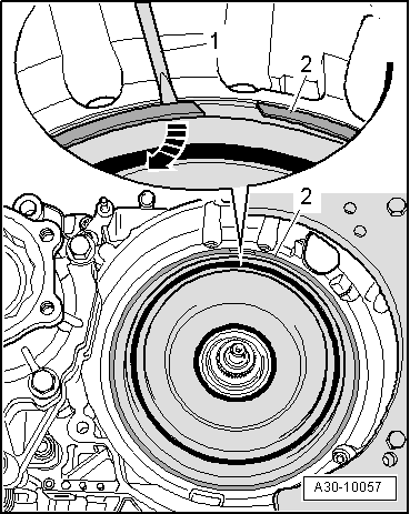
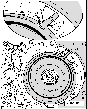
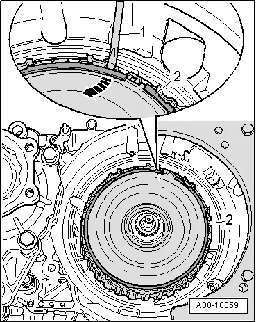
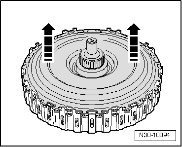
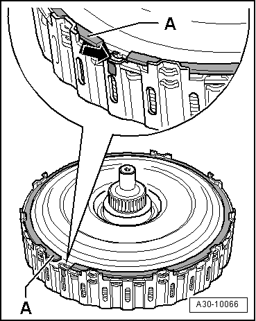
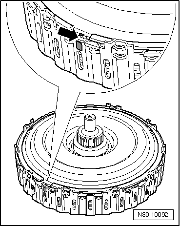
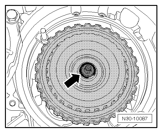
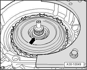
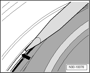
The drive plate of a new clutch is not secured with a circlip; it is only a “close fit” in the clutch.
t  
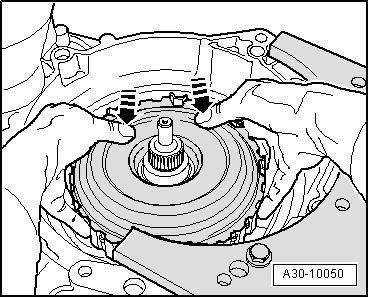
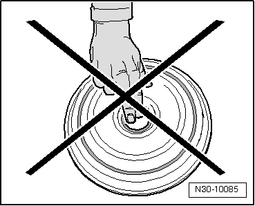
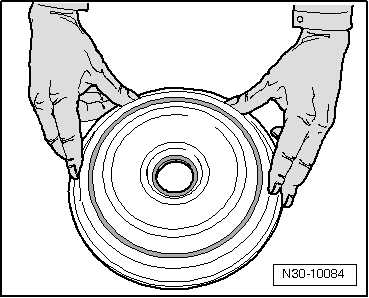
While carrying out the following steps you must therefore hold the drive plate by pressing it into the outer plate carrier with both thumbs.
t  The drive plate must remain engaged between the splines of the outer plate carrier.
t  If the drive plate comes loose, the clutch plates can slip out of position inside the multiple clutch unit. If this happens, it may not be possible to adjust the multiple clutch correctly during installation.
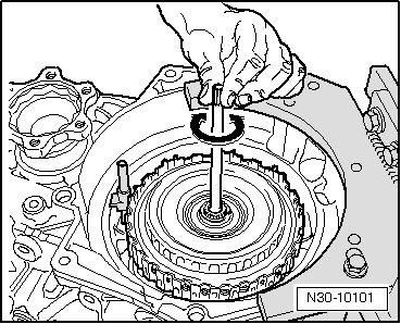
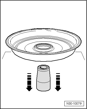
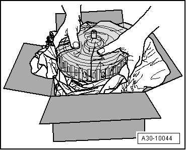
–  Take the circlip out of the packaging.
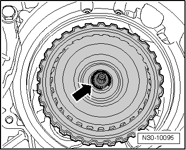
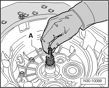
–  Take the clutch for direct shift gearbox out of the packaging, at the same time pressing the drive plate into the outer plate carrier with both thumbs.
  A30-10044
–  Secure drive plate in outer plate carrier with “old” circlip -A- from removed clutch.
l  Do NOT use the new circlip supplied when carrying out this installation.
l  The circlip must be installed so that the lug on the drive plate -arrow- and the colour-marked splines on the outer plate carrier are located between the two ends of the circlip.
l  The circlip must be fully engaged all round.
  A30-10066
–  Check that the 4 oil seals on the hub on the underside of the multiple clutch are correctly seated; engage in position if necessary.
l  The joints of the seals should be offset and not aligned one above the other.
  N30-10091
–  Apply retaining pin -T10303- to seat of clutch end cover as illustrated.
  N30-10098
–  Install multiple clutch in clutch bell housing (turn and move up and down as required); do not allow clutch to drop into place. While doing this, keep the drive plate pressed into the outer plate carrier with both thumbs -arrows-.
  A30-10050
l  During this procedure the retaining pin -T10303- must be held in place by a 2nd mechanic.
  Note
t  The retaining pin remains in position until the clutch end cover is installed.
t  The multiple clutch must not be turned from this point onwards, as this would turn the retaining pin -T10303- out of position.
  A30-10051
–  Check whether the projecting lug -arrow- on the drive plate is positioned between the colour-marked splines on the outer plate carrier.
If no markings are provided:
–  Mark position of projecting lug in relation to outer rim of outer plate carrier with waterproof pen as illustrated.
l  When re-assembling, the lug on the drive plate must be located again at this marked position.
  N30-10092
l  While carrying out the following two steps the retaining pin -T10303- must be held in place by a 2nd mechanic.
  A30-10051
–  Pry out the old circlip -2- using a screwdriver -1--arrow-.
  Caution
DO NOT remove or lift up the inner plate carrier. This could cause the plates to move out of their original positions.
  A30-10059
–  With clutch in position, lift out drive plate -arrows-; if necessary pry drive plate carefully out of splines on outer plate carrier using a screwdriver.
–  Lay drive plate aside.
  N30-10094
Determining thickness of circlip for multiple clutch
–  Select the 2 mm thick circlip from the circlips supplied with the clutch and fit this circlip as shown -arrow-.
  Note
This circlip is installed provisionally in order to measure the axial play.
  N30-10087
–  Bolt universal dial gauge bracket -VW 387- onto gearbox flange.
–  For 1st measurement, apply tip of dial gauge to end of input shaft as shown in illustration.
–  Set dial gauge to “0” with a preload of 2 mm.
–  Lift up clutch as far as it will go and note dial gauge reading (= axial play of input shaft).
  N30-10096
–  For 2nd measurement, apply tip of dial gauge to hub of inner plate carrier as shown in illustration.
l  The tip of the dial gauge must not contact the circlip.
–  Set dial gauge to “0” with a preload of 2 mm.
–  Lift up clutch again as far as it will go and note dial gauge reading.
The thickness of the new circlip is calculated according to the following formula:
   2nd measurement – 1st measurement + 1.85 mm = thickness of circlip
The thickness of the new circlips -02E 311 321- is graduated in steps of 0.1 mm. When selecting the required circlip, round up or down to the nearest 10th of a millimetre as required. In other words, values up to 0.049 are rounded down and values of 0.05 and above are rounded up.
  N30-10100
Calculated thickness of new circlipNew circlip
2.27 mm2.3 mm
2.24 mm2.2 mm

   
–  Remove provisionally fitted circlip (2.0 mm) and fit new circlip with thickness as calculated above.
  Note
t  If the calculated thickness of the new circlip is exactly 2.0 mm, the circlip fitted previously for taking the measurement does not have to be removed.
t  All remaining circlips should be disposed of.
t  Circlips may not be used more than once.
  N30-10087
–  Insert pump shaft.
  Note
When installing, lift the shaft and turn it slightly -arrow- so that it slides in and engages fully in the splines.
  N30-10101
–  Install drive plate in multiple clutch.
l  The projecting lug on the drive plate must be positioned between the colour-marked splines on the outer plate carrier. Alternatively, align the new markings made earlier in this procedure.
  N30-10092
–  Install new circlip securing drive plate.
l  The circlip must be installed so that the lug on the drive plate and the colour-marked splines on the outer plate carrier are located between the two ends of the circlip.
l  The circlip must be fully engaged all round.
–  Use a screwdriver to check that the circlip is properly seated and fully engaged.
–  Take out retaining pin -T10303- between multiple clutch and housing.
  N30-10090
Installing clutch end cover
  Note
Renew clutch end cover and circlip.
–  Thoroughly degrease running surface -arrow- on drive plate for oil seal of clutch end cover.
  Caution
The contact surfaces of the clutch end cover must be cleaned very thoroughly, otherwise leaks can occur.
  A30-10049
–  Clean contact surface for outer seal of clutch end cover.
  Caution
t  Do not touch the seal inside the opening in the clutch end cover. This seal will only seal properly if the running surface is absolutely free of grease when installed.
t  Do not apply hammer blows directly to the clutch end cover. Any force applied to the inner part of the clutch end cover will cause malfunctions.
  N30-10085
–  Take the new clutch end cover out of its packaging. Always take hold of the outside of the clutch end cover, as illustrated. DO NOT touch the seal inside the cover.
–  Clean end of gearbox shaft if necessary.
  Note
t  Lightly lubricate the outer seal only.
t  If there are any stickers on the inside or the outside of the end cover, remove them thoroughly.
  N30-10084
–  Place assembly sleeve -T10302- on a flat surface.
–  The seal in the centre of the clutch end cover must be pre-formed before installation; this is done by guiding the new clutch end cover with the outside pointing downwards horizontally and evenly over the entire length of the assembly sleeve -arrows-.
  N30-10079
–  Remove assembly sleeve upwards from clutch end cover and fit assembly sleeve onto end of clutch shaft.
–  Guide clutch end cover with the outside pointing upwards horizontally over sleeve -arrows- and press cover evenly onto its seat.
  A30-10083
–  If necessary use a screwdriver to lever the clutch end cover carefully into its seat, as illustrated, so that the new circlip can be fitted.
–  Install new circlip for clutch end cover into gearbox housing.
  Note
To make sure circlip remains in groove always counterhold on opposite side if necessary.
l  The circlip must be fully engaged all round and must be properly seated in the base of the groove.
–  Use a screwdriver to check that the circlip is properly seated and fully engaged.
–  Fill up gear oil → Chapter.
–  After installing the gearbox, run the Basic setting function in Guided Functions → vehicle diagnostic tester.
  N30-10078

Gearbox mechanics,operation, construction,diff. > < Exploded view - multiple clutch