audi Workshop Repair Guides

Audi Workshop Service and Repair Manuals

Checking function of ignition key removal lock > < Checking selector mechanism
Checking and adjusting selector lever cable
Special tools and workshop equipment required
   
t  
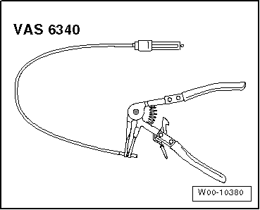
Hose clip pliers -VAS 6340-
Checking adjustment of selector lever cable
l  Selector mechanism checked → Chapter.
–  Keep button pressed, while pulling selector lever approx. 5 mm to the rear out of position “P”. Then keep lever in this position, do not move it into “R”.
–  Release selector lever.
l  The selector lever should spring back into position “P” automatically.
–  If necessary, adjust selector lever → Anchor.
–  Shift selector lever into position “N”.
–  Keep button pressed, while pulling selector lever approx. 5 mm to the rear out of position “N”. Then keep lever in this position, do not move it into “D”.
–  Release selector lever.
l  The selector lever should spring back into position “N” automatically.
–  If necessary, adjust selector lever → Anchor.
–  Keep button pressed, while pushing selector lever approx. 5 mm to the front out of position “N”. Then keep lever in this position, do not move it into “R”.
–  Release selector lever.
l  The selector lever should spring back into position “N” automatically.
–  If necessary, adjust selector lever → Anchor.
–  → Chapter „Checking selector mechanism“.
Adjusting selector lever cable
–  Switch off ignition.
  W00-10380
Vehicles with 4-cylinder 2.0 ltr. TFSI engine:
There are two different versions of this engine.
Version 1 (with air cleaner housing at side):
–  Unplug electrical connector -1- from air mass meter -G70-.
–  Remove air hose -2-.
–  Remove bolt -4- and remove air cleaner housing.
  Note
-Item 3- can be disregarded.
  A10-10760
Version 2 (with air cleaner housing in engine cover panel):
–  Unplug electrical connector -3- from air mass meter -G70-.
–  Release clamps -1 and 2- and disconnect air hose from air mass meter.
–  Release spring-type clips -4- and detach air intake hose from engine cover panel.
  A24-10616
  Caution
Risk of breaking engine cover panel.
It is important to observe the removal sequence.
–  Carefully detach engine cover panel from positions -1, 2, 3, 4- one after the other.
  A24-10615
Vehicles with 6-cylinder 3.2 ltr. engine:
–  Detach vacuum hose -2- at air intake hose.
–  Detach air intake hose -1- at throttle valve module -J338-.
–  Unplug electrical connector for air mass meter -G70--3-.
–  Unbolt air cleaner (top section) -arrow-.
–  Remove filter element.
  A10-1879
–  Unbolt air cleaner (bottom section) -arrows-.
  A10-1880
Continued for all vehicles:
–  Shift selector lever into position “P”.
–  Make sure that securing clip -A- is pressed all the way down and properly seated.
  Note
Items -1, C and D- can be disregarded.
–  Move selector lever from “P” to “S”.
–  Check protective sleeve on selector mechanism (on front of selector lever cable) for damage, if necessary renew cable.
–  Shift selector lever into position “P”.
l  The selector mechanism and selector lever cable should move smoothly; if necessary renew selector lever cable → Chapter or renew selector mechanism: up to 11.2009 → Chapter, from 11.2009 onwards → Chapter.
–  Loosen bolt -B-.
–  Move gearbox selector lever into position “P” on gearbox.
–  Turn both front wheels in one direction, e.g. by pushing the vehicle forwards, until the detent lever in the gearbox engages in the parking lock gear and the wheels are blocked (it is not possible to turn them both in the same direction simultaneously).
  Note
The selector lever in the selector mechanism must remain in position “P” when clamping bolt -B- is loosened, otherwise the adjustment will not be correct.
–  Carefully move selector lever slightly forwards and backwards without shifting lever into a different selector lever position.
  Note
The selector lever cable is then relieved of stress.
–  Tighten bolt -B- smoothly and evenly (tightening torque: 13 Nm).
  Note
When tightening bolt -B-, make sure the selector lever cable does not move out of position.
–  Perform installation of all components in reverse sequence.
  A37-0659

Checking function of ignition key removal lock > < Checking selector mechanism