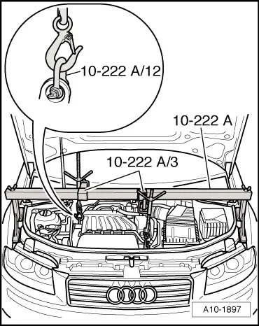
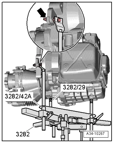
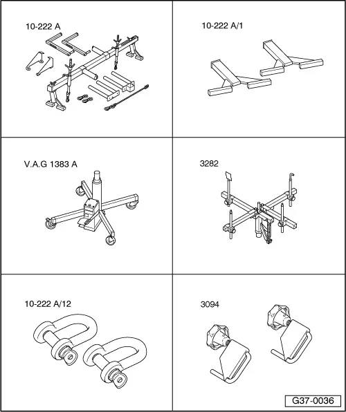
| To remove direct shift gearbox 02E, set up gearbox support -3282- with adjustment plate -3282/42 A- and place on engine and gearbox jack -V.A.G 1383 A-. |
| –
| Align arms of gearbox support according to holes in adjustment plate -3282/42 A-. |
| –
| Secure support elements as illustrated on adjustment plate -3282/42 A-. However, use -retainer plate with drilling- as front support element. |
| –
| Place engine and gearbox jack -V.A.G 1383 A- underneath vehicle. |
| l
| The arrow symbol on the adjustment plate points in the direction of travel. |
| –
| Align gearbox support -3282- parallel with gearbox. |
| –
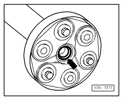
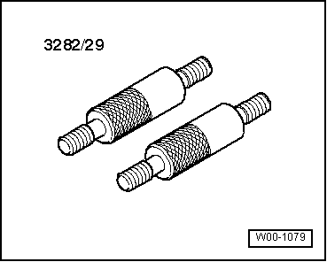
| Screw pin -3282/29- into gearbox. |
| –
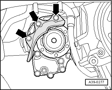
| Secure -retainer plate with drilling- firmly to gearbox as illustrated -arrow-. |
| –
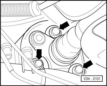
| Insert last support element in gearbox as illustrated. |
| –
| Support the gearbox by raising the engine and gearbox jack -V.A.G 1383 A- from below. |
| –
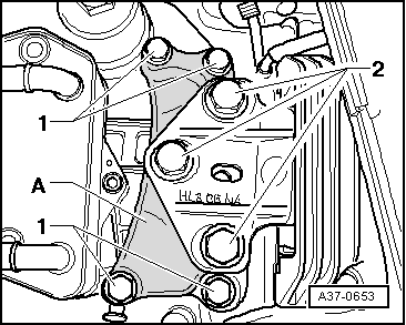
| Remove remaining engine/gearbox securing bolts. |
| –
| Press gearbox off dowel sleeves. |
| –
| Pull the gearbox off engine first from the bevel box side and then from the front side. |
| –
| Lower gearbox carefully using engine and gearbox jack -V.A.G 1383 A-; make sure no wires or hoses become trapped. |
| –
| When lowering the gearbox, change position of gearbox using the spindles on gearbox support -3282-. |
|
|
|

 Note
Note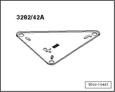
 Caution