
A3 Mk2
| Removing gearbox (vehicles with 2.0 ltr. TDI common rail engine) |
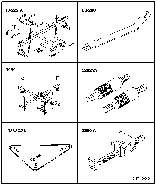
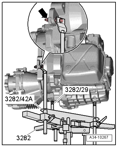
| Special tools and workshop equipment required |
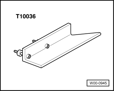
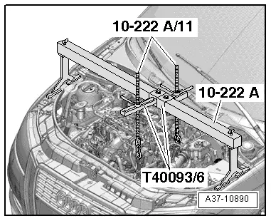
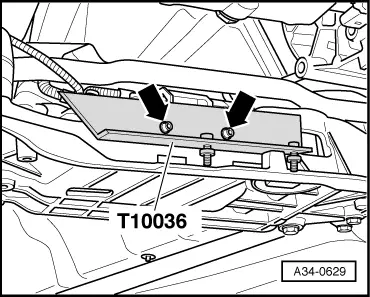
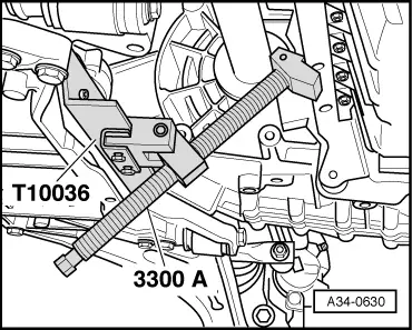
| t | Support bracket -10 - 222 A- |
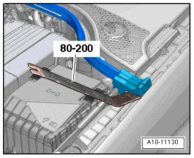
| t | Removal lever -80 - |
| t | Gearbox support -3282- |
| t | Pin -3282/29- |
| t | Adjustment plate -3282/42 A- |
| t | Engine support -3300 A- |
|
|
|
|
|
|
|
|
 Note
Note
|
|
Note
|
|
|
|
Note
|
|
|
|
|
|
Note
|
|
Note
|
|
 Caution
|
|
|
|
|
|
Note
|
|
|
|
|
|
|
|
|
|
Note
|
|
|
|
|
|
|
|
|
|
|
|
|
|
|
|
 WARNING
Note
|
|
|
|
|
|
|
|
|
|
Note |
|
Note |
|
|
|
|
|
|
|