
A3 Mk2

| Special tools and workshop equipment required |
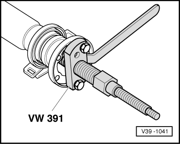
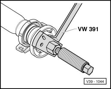
| t | Drive flange installing tool -VW 391- |
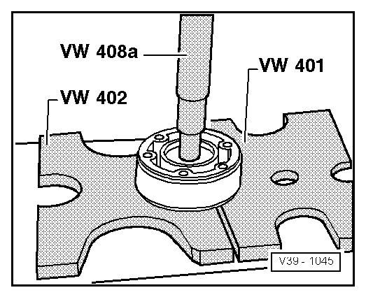
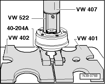
| t | Thrust plate -VW 401- |
| t | Thrust plate -VW 402- |
| t | Press tool -VW 407- |
| t | Press tool -VW 408A- |
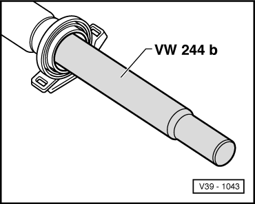
| t | Drift sleeve -VW 244B- |

| t | Support sleeve -VW 522- |
| t | Tensioner -40-204A- |
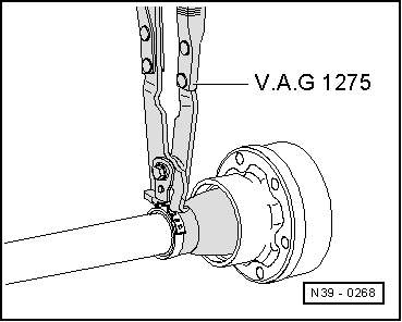
| t | Hose clip pliers -V.A.G 1275/- |
| t | Torque wrench -V.A.G 1331/- |
| t | Circlip pliers -VW 161A- |
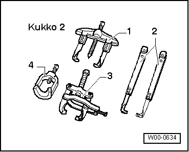
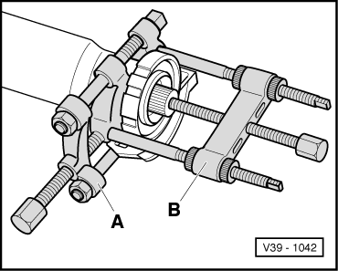
| t | Puller -2 - Kukko 18/0- |
| t | Splitter -3 - Kukko 17/1- |
|
|
|
|
|
|
 Note
Note
|
|
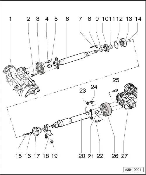
| 1 - | Manual gearbox with bevel box |
| 2 - | Bolt |
| q | 50 Nm + 90° |
| q | Always renew |
| 3 - | Flexible coupling with heat shield |
| q | Installation position: open side of heat shield points towards gearbox |
| q | Removing and installing → Chapter |
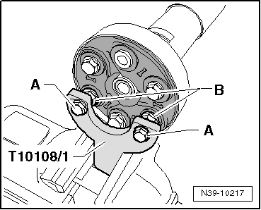
| 4 - | Bolt |
| q | 60 Nm |
| q | Allocation → Fig. |
| 5 - | Centring sleeve |
| 6 - | Propshaft tube (front) |
| q | Do not damage centring sleeve -5- and seal in centre of flange when removing and installing |
| 7 - | Bolt |
| q | 40 Nm |
| 8 - | Lock plate |
| 9 - | Clamp |
| q | Tightening → Fig. |
| 10 - | Boot for constant velocity joint |
| q | Drive off with a drift before pressing off CV joint |
| q | Check for damage |
| 11 - | Dished spring |
| q | Inner diameter serrated |
| q | Installation position: large diameter lies against CV joint |
| 12 - | Gasket |
| q | Renew; pull off backing and stick onto joint |
| 13 - | Constant velocity joint |
| q | Pressing off → Fig. |
| q | Pressing on → Fig. |
| q | Press 25 g G-6.3 grease from each side (in total 50 g) into joint. Regrease joint if necessary when renewing boot |
| 14 - | Circlip |
| q | Renew |
| q | Remove and install using circlip pliers -VW 161A- |
| 15 - | Bolt |
| q | 45 Nm |
| 16 - | Washer |
| q | Always renew |
| 17 - | Flange |
| q | Pulling off → Fig. |
| q | Pulling on → Fig. |
| 18 - | Centre bearing |
| q | Pulling off → Fig. |
| q | Installation position → Fig. |
| q | Driving on → Fig. |
| 19 - | Bolt |
| q | 25 Nm |
| q | Also secures heat shield |
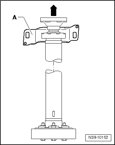
| 20 - | Propshaft tube (rear) |
| q | Do not damage centring sleeve -5- and seal in centre of flange when removing and installing |
| q | Clamp in a vice to loosen and tighten bolt connections → Fig. |
| 21 - | Centring sleeve |
| 22 - | Bolt |
| q | 60 Nm |
| q | Allocation → Fig. |
| 23 - | Balancing nut |
| q | 10 Nm |
| q | Not fitted on all propshafts |
| q | If the flange bolt → Item was loosened, the balancing nut and the balancing washer → Item must NOT be re-installed. |
| 24 - | Balancing washer |
| q | Only fitted on balanced final drive units |
| 25 - | Bolt |
| q | 50 Nm + 90° |
| q | Always renew |
| 26 - | Flexible coupling with vibration damper |
| q | Installation position → Fig. |
| 27 - | Rear final drive |
| q | Removing and installing → Chapter |
|
|
|
|
|
|
|
|
|
|
|
|
|
|
|
|
|
|
|
|