audi Workshop Repair Guides

Audi Workshop Service and Repair Manuals

Checking compression > < Cylinder head - exploded view
Removing and installing cylinder head
   
Removing and installing cylinder head
Special tools and workshop equipment required
t  Support bracket -10 - 222 A-
t  Hook -10 - 222 A /10-
t  Spindle -10 - 222 A /11-
t  Shackle -10 - 222 A /12-
t  Spark plug socket and extension -3122 B-
t  Retainer -T10014-

   
Special tools and workshop equipment required
t  Dial gauge -VAS 6079-
t  Puller -T10094-
t  Adapter for dial gauge -T10170-
t  Camshaft clamp -T10171 A-
t  Counterhold tool -T10172-
t  Locking pin -T40011-

   
t  Adapter -T40093/6- from engine support bracket (supplementary set) -T40093-
t  Sealant → Electronic parts catalogue
Removing
–  Reduce fuel pressure in high-pressure section of injection system → Rep. Gr.24.
–  Drain coolant → Chapter.
–  Remove alternator → Electrical system; Rep. Gr.27.
–  Remove poly V-belt pulley for coolant pump → Chapter.
–  Removing idler roller for poly V-belt → Chapter.
–  Remove intake manifold → Rep. Gr.24.
–  Remove catalytic converter → Chapter.
–  Remove sump → Chapter.
–  Remove thermostat housing → Chapter
–  Remove bracket for air conditioner compressor → Rep. Gr.87.
  W00-10354
–  Disengage coolant hose -1- at engine cover panel.
–  Pull oil dipstick -2- out of guide tube.
–  Unscrew bolts -arrows- and remove engine cover panel.
  A10-10950
–  Disconnect fuel supply pipe -2- (pull release ring).
–  Disconnect line -1- going to activated charcoal filter (press release tab).
  A10-10762
–  Release activated charcoal filter -arrow B-, lift off -arrow A- and move clear to one side with line -1- connected.
  A20-10447
–  Remove bracket -3- for activated charcoal filter.
–  Remove bolt on filler neck -2- for washer fluid reservoir.
–  Detach electrical connector at coolant shortage indicator switch -F66- on coolant expansion tank and move wiring harness clear.
–  Remove bolts for coolant expansion tank -1- and place coolant expansion tank on top of engine with the hoses attached (secure if necessary).
  A13-0646
–  Loosen bolts -arrows- of assembly mounting at engine approx. 2 turns.
  A10-10019
–  Remove bolt -4- and detach crankcase breather hose from turbocharger -arrow-.
–  Detach crankcase breather hose -1- from timing chain cover (press release tabs and take off with lines -2- and -3- still connected).
  A13-10522
–  Remove bolts -1, 3, 4, 5-.
–  Disconnect coolant lines from turbocharger and move clear to one side.
  Note
Disregard -item 2- and -3094-.
  A21-10242
–  Remove banjo bolt -1- and bolts -2, 3, 4-, detach oil supply pipe and retaining plate from turbocharger.
  A21-10243
–  Remove bolts -2- for oil return pipe (top).
  Note
Disregard -item 1-.
  A21-10170
–  Unplug electrical connector -1- on charge pressure control solenoid valve -N75- and -2- on turbocharger air recirculation valve -N249-.
  A21-10241
–  Apply puller -T10094 A- to all ignition coils -arrow-, pull out ignition coils and at the same time unplug electrical connectors at ignition coils for cylinders 1 ... 4.
–  Remove spark plug for cylinder 1 with spark plug socket and extension -3122 B-.
  A15-10530
–  Unplug electrical connectors -1, 2, 4-, detach wiring duct -3- from camshaft housing and swivel to left side.
  A15-10538
  WARNING
The fuel system operates at extremely high pressure. This can cause injury.
The fuel pressure in the high-pressure section of the injection system must be reduced to a residual pressure prior to opening the system.
–  Remove union nuts -arrows- and bolt -1- and detach high-pressure pipe.
–  Unplug electrical connector -2- on fuel pressure regulating valve -N276-.
–  Unplug electrical connectors at injectors and move clear.
  A15-10540
–  Screw adapter for dial gauge -T10170- into spark plug hole as far as the stop.
–  Insert dial gauge -VAS 6079- with extension -T10170/1- as far as the stop and secure using locking nut -arrow-.
–  Rotate crankshaft in normal direction of rotation to “TDC”.
l  “TDC” = maximum measured value on dial gauge.
  N15-0653
–  Remove bolts -arrows- and detach sealing caps -1- and -2-.
  A15-10531
l  The threaded holes -arrows- in the camshafts must be positioned as shown in illustration. Turn crankshaft one turn (360°) if necessary.
  N15-0657
–  Insert camshaft clamp -T10171 A- into holes in camshafts as far as stop.
l  The locking pins -arrows 1- must engage in the holes -arrows 2-.
l  The inscription “TOP”-arrow 3- should be legible from above.
  A15-10532
–  To secure the camshaft clamp -T10171 A-, screw in an M6 bolt -arrow- hand-tight, but do not tighten.
  Caution
Avoid damage to camshafts.
The camshaft holder -T10171 A- must not be used as a counterhold tool.
  A15-10533
–  Remove bolts -1- and -3- and take off bracket -2- for coolant pipe (right-side).
  A15-10539
–  Unscrew plug -arrow- for “TDC” hole on cylinder block.
  A13-10524
–  Screw locking pin -T10340- into cylinder block as far as stop and tighten to 30 Nm.
  Note
The locking pin -T10340- locks the crankshaft only in the direction of engine rotation.
  A13-10525
  Caution
Risk of damage to engine.
To prevent the crankshaft chain sprocket from slipping off the drive lug, do not rotate the crankshaft after the poly V-belt pulley has been detached.
–  Loosen bolt for poly V-belt pulley using counterhold tool -3415- with pin -3415/1-.
–  Remove bolt and take off poly V-belt pulley.
  N13-0469
–  Set up support bracket -10 - 222 A- with hook -10 - 222 A /10-, spindle -10 - 222 A /11- (2x) and adapter -T40093/6- on top edges of body flanges (left and right), as shown in illustration.
–  Attach hook -10 - 222 A /10- in right engine lifting eye and tighten spindle slightly to take up weight of engine/gearbox assembly.
  A15-10541
–  Remove bolts -1- and -2- and detach connecting bracket.
–  Remove bolts -3 ... 6- and detach engine mounting.
  A13-0647
–  Remove bolts -1 ... 6- and -arrows- for timing chain cover.
–  Raise engine slightly and remove timing chain cover.
–  Use drift to drive out oil seal.
  A13-10414
–  Insert bush -2- and screw in crankshaft pulley bolt -1- hand-tight to secure chain sprocket on crankshaft.
  A13-10093
–  Press tensioning rail -2- in direction of -arrow- and use locking pin -T40011- to lock piston for chain tensioner -1-.
  Caution
If a used timing chain rotates in the opposite direction when it is refitted, this can cause breakage.
Mark running direction of timing chain with coloured arrows for re-installation. Do not mark timing chain by means of centre punch, notch or the like.
Avoid damage to camshafts.
The camshaft holder -T10171 A- must not be used as a counterhold tool.
Risk of damage to thread.
The camshaft adjuster central bolt has a left-hand thread.
  A13-10095
–  Loosen bolt -2- for camshaft adjuster -1- and bolt -4- for camshaft chain sprocket -5-, using counterhold tool -T10172- to counterhold on camshaft chain sprocket.
–  Detach camshaft chain sprocket together with camshaft timing chain -3-.
  Note
Leave camshaft adjuster on camshaft.
  N15-0686
–  Loosen locking nut -arrow- and detach adapter for dial gauge -T10170- with dial gauge -VAS 6079-.
  N15-0653
–  Pull off tensioning rail -1- and guide rail -2- from mounting pins.
  A13-10051
–  Slacken camshaft housing bolts in the sequence -15 ... 1-.
  Note
Bolt -14- below turbocharger remains in camshaft housing.
–  Carefully detach camshaft housing to the right.
–  Mark original positions of roller rocker fingers and compensation elements for reinstallation.
–  Remove roller rocker fingers together with compensation elements and put down on a clean surface.
  A15-10544
–  Secure retainer -T10014- in threaded hole in cylinder block as shown in illustration and tighten to 40 Nm.
  A15-10542
–  Attach spindle -10 - 222 A /11- (right-side) to retainer -T10014-.
–  Attach spindle -10 - 222 A /11- (left-side) with hook -10 - 222 A /2- and shackle -10 - 222 A /12- to gearbox.
–  Take up weight at both spindles, detach hook -10 - 222 A /10- and move to side.
  A15-10545
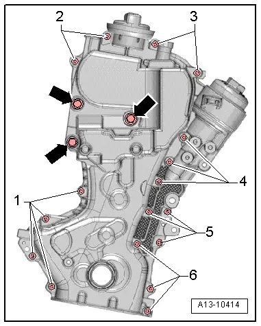
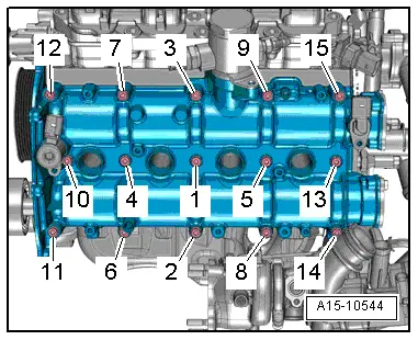
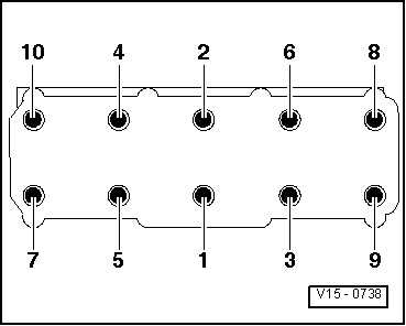
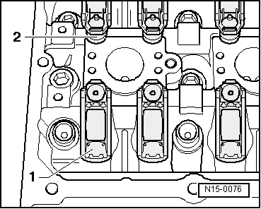
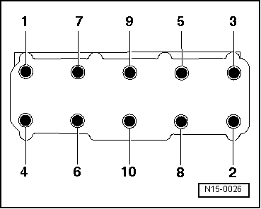
–  Slacken cylinder head bolts in the sequence -1 ... 10-.
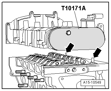
–  Remove bolts and carefully take off cylinder head.
–  Place cylinder head onto soft surface (foam plastic).
Installing
l  Tightening torques → Chapter
  Caution
Avoid damage to sealing surfaces.
t  Carefully remove sealant residue from cylinder head and cylinder block.
t  Ensure that no long scores or scratches are made on the surfaces.
Avoid damage to cylinder block.
No oil or coolant must be allowed to remain in the blind holes for the cylinder head bolts in the cylinder block.
Risk of leaks at cylinder head gasket.
t  Carefully remove any sealant residue from the cylinder head and cylinder block. Ensure that no long scores or scratches are made on the surfaces.
t  Carefully remove any remaining emery and abrasive material.
t  Do not remove new cylinder head gasket from packaging until it is ready to be fitted.
t  Handle the cylinder head gasket very carefully to prevent damage to the silicone coating or the indented area of the gasket.
Avoid damage to open valves.
When installing an exchange cylinder head, the plastic protectors fitted to protect the open valves should not be removed until the cylinder head is ready to be fitted.
  Note
t  Renew the bolts tightened with specified tightening angle.
t  Renew self-locking nuts as well as seals, gaskets and O-rings.
t  
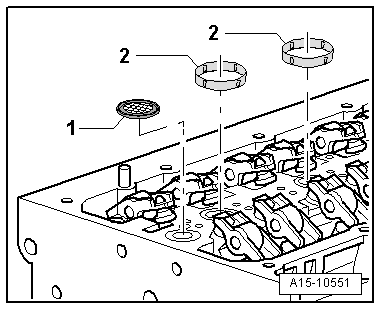
Renew oil strainer in cylinder head.
t  When installing an exchange cylinder head, the contact surfaces between the hydraulic compensation elements, roller rocker fingers and cams must be oiled before installing the cylinder head cover.
t  Secure all hose connections with the correct type of hose clips (same as original equipment) → Electronic parts catalogue.
t  After fitting a new cylinder head or cylinder head gasket, change the engine oil and the coolant in the entire cooling system.
  Caution
Protect lubrication system and bearings against contamination.
Cover exposed parts of the engine.
–  Remove sealant residue on cylinder head and camshaft housing using commercially available sealant remover.
–  Clean sealing surfaces; they must be free of oil and grease.
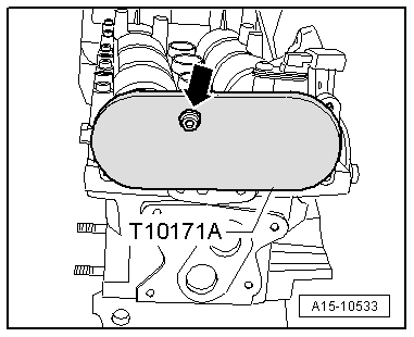
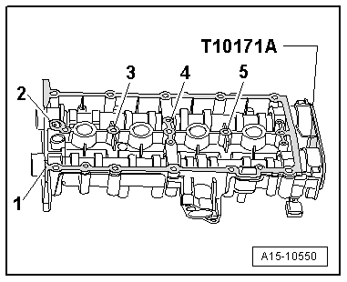
–  Check that crankshaft is still positioned at “TDC” and then turn back in the opposite direction of engine rotation by approx. 45°.
–  Place cylinder head gasket in position.
l  Installation position: Part No. must be visible.
l  Note position of dowel sleeves in cylinder block.
–  Fit cylinder head.
  N15-0026
–  Tighten cylinder head bolts → Fig..
  Note
Cylinder head bolts do not have to be torqued down again later after repair work.
  V15-0738
l  Camshaft clamp -T10171 A- must be fitted and secured with a bolt -arrow- before installing camshaft housing.
  A15-10533
–  Ensure all roller rocker fingers contact the valve ends -1- correctly and are clipped into their respective support elements -2-.
  N15-0076
  Caution
Make sure lubrication system is not clogged by excess sealant.
The sealant bead must not be thicker than specified.
–  Apply a thin and even layer of sealant to the clean sealing surface of the camshaft housing at grey-shaded areas -1 ... 5- shown in illustration.
  Note
The camshaft housing must be installed within 5 minutes after applying the sealant.
  A15-10550
–  Fit new oil strainer -1- into cylinder head.
–  Fit 4 seals -2- into cylinder head.
  A15-10551
  Caution
Make sure remnants of oil are removed before fitting, otherwise leakage can occur.
Make sure sealing surfaces are free of oil when fitting camshaft housing.
–  Carefully fit the camshaft housing vertically onto the dowel pins -arrows- on cylinder head from above.
  Note
Make sure that camshaft housing is kept straight.
  A15-10549
–  Tighten camshaft housing bolts → Fig..
  Note
After fitting camshaft housing, allow sealant to dry for approx. 30 minutes.
  A15-10544
–  Fit tensioning rail -1- and guide rail -2- onto mounting pins.
–  Install camshaft timing chain → Anchor.
Installation is carried out in the reverse order; note the following:
  Caution
Avoid damage to valves and piston crowns after working on valve gear.
Turn the engine carefully at least 2 rotations to ensure that none of the valves make contact when the starter is operated.
–  Install sump → Anchor.
–  Install intake manifold → Rep. Gr.24.
–  Install thermostat housing → Chapter.
–  Install catalytic converter → Chapter.
  A13-10051

Checking compression > < Cylinder head - exploded view