audi Workshop Repair Guides

Audi Workshop Service and Repair Manuals

Enginecrankshaft group, pistons > < Checking adjustment
Adjusting engine mountings
Special tools and workshop equipment required
   
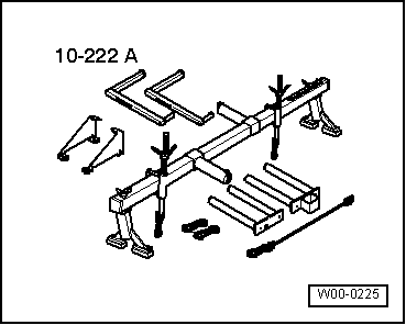
t  Support bracket -10-222 A-
  W00-0225
Procedure
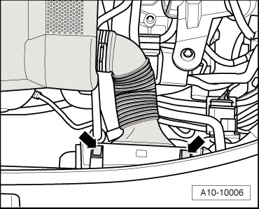
–  Unclip air intake hose from air duct -arrows-.
  A10-10006
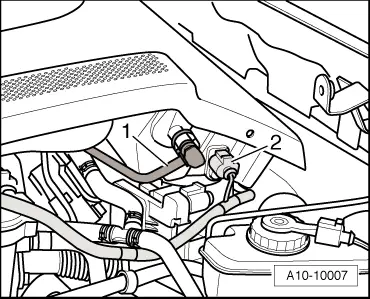
–  Unplug electrical connector at intake air temperature sender 2 -G299--item 2-.
–  Detach vacuum hose -1- from actuator for intake air preheater.
  A10-10007
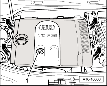
–  Pull dipstick -1- out of guide tube.
–  Remove the engine cover together with air cleaner housing -arrows-.
–  Re-insert dipstick in guide tube.
  A10-10008
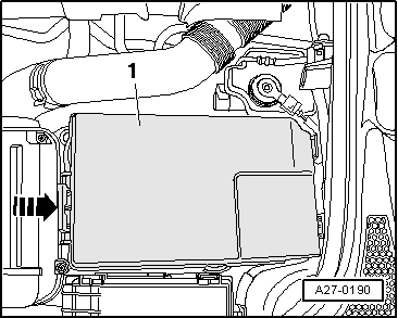
–  Remove cover -1- over battery. To do so, press release tab -arrow-.
  A27-0190
  Caution
Observe notes on procedure for disconnecting the battery → Rep. Gr.27.
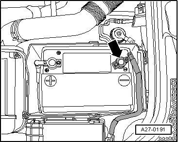
–  With ignition switched off, disconnect battery earth cable -arrow-.
  A27-0191
–  Remove battery → Rep. Gr.27.
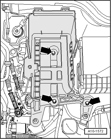
–  Remove battery tray -arrows-.
–  Detach battery tray from front of air duct.
  A10-1572
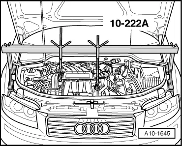
Vehicles with manual gearbox:
–  Set up support bracket -10-222 A- on wing panel flanges.
l  The spindles face forwards.
–  Detach crankcase breather hose from oil filler neck.
–  Attach hooks of spindles to lifting eyes.
–  Take up weight of engine evenly with both spindles (but do not raise engine).
  A10-1645
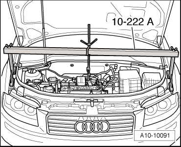
Vehicles with automatic gearbox:
–  Set up support bracket -10-222 A- on wing panel flanges.
–  Hook spindle of lifting tackle onto left-side engine lifting eye.
–  Take up weight of engine with the spindle, but do not lift.
  A10-10091
All models:
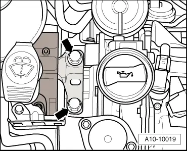
–  Renew the bolts for assembly mounting at engine -arrows- one by one (if not already renewed when engine was installed).
–  Screw in new bolts initially finger-tight.
  A10-10019
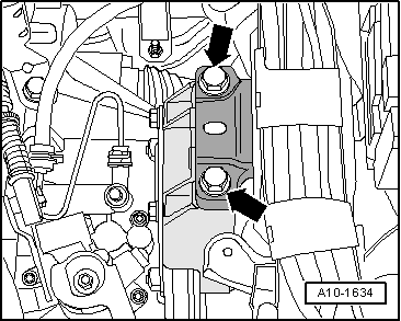
–  Renew the bolts for assembly mounting at gearbox -arrows- one by one (if not already renewed when engine was installed).
–  Screw in new bolts initially finger-tight.
  A10-1634
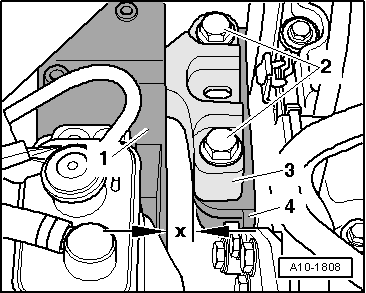
–  Using a tyre iron, adjust engine between engine console -1- and support arm -3- until the specifications listed below are obtained:
l  Both bolt heads -2- must be parallel to the edge of the support arm -3-.
l  There must be a distance of -x- = 12 mm between engine console -1- and engine support -4-.
  Note
Distance -x- = 12 mm can also be checked with a metal rod of suitable size.
–  Tighten the bolts for engine assembly mounting.
  A10-1808
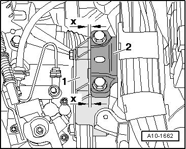
–  On the gearbox side, check that the edges of the support arm -2- and gearbox support -1- are parallel (distance -x- = distance -x-).
–  Tighten the bolts for gearbox assembly mounting.
Installation is carried out in the reverse order; note the following:
–  Install battery → Rep. Gr.27.
Tightening torques
  A10-1662
ComponentNm
Support arm to engine support60 + 90° 1)2)
Support arm to gearbox support60 + 90° 1)2)
l  1) Renew bolts.
l  2) 90° = one quarter turn.


Enginecrankshaft group, pistons > < Checking adjustment