audi Workshop Repair Guides

Audi Workshop Service and Repair Manuals

Adjusting engine mountings > < Securing engine to assembly stand
Installing engine
Installing engine
Installation is carried out in the reverse order; note the following:
  Note
t  Renew self-locking nuts and bolts when performing assembly work.
t  Renew bolts which are tightened to a specified angle as well as oil seals and gaskets.
t  Tightening torques apply only to lightly greased, oiled, phosphated or black-finished nuts and bolts.
t  Additional lubricant such as engine oil or gearbox oil may be used, but do not use lubricant containing graphite.
t  Do not use degreased parts.
t  Tolerance for tightening torques ± 15 %.
t  Secure all hose connections with the correct type of hose clips (same as original equipment) → Parts catalogue.
t  Reinstall all cable ties in the same locations when assembling.
   
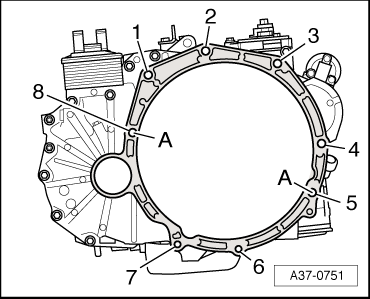
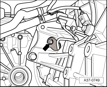
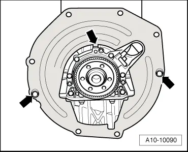
–  Check whether dowel sleeves for centring the engine/gearbox assembly are fitted in the cylinder block; install if necessary.
–  Engage intermediate plate on sealing flange and slip onto dowel sleeves -arrows-.
Vehicles with manual gearbox:
–  Clean splines of input shaft and (on used clutch plates) splines of hub.
–  Remove any traces of corrosion and apply a very thin coat of grease -G 000 100- onto splines.
–  Then move clutch plate back and forth on input shaft until the hub moves smoothly on the shaft. Remove any excess grease.
–  Check that clutch plate is correctly centred → Rep. Gr.30.
–  Check clutch release bearing for wear, renew if necessary.
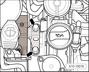
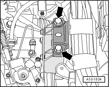
–  Bolt gearbox to engine.
  Note
t  Tightening torques apply only to lightly greased, oiled, phosphated or black-finished nuts and bolts.
t  Additional lubricant such as engine oil or gearbox oil may be used, but do not use lubricant containing graphite.
t  Do not use degreased parts.
t  Tolerance for tightening torques ± 15%.
  A10-10090
Securing engine to manual gearbox
  A34-0665
ItemBoltNm
1, 2, 5M12x6580
3M12x13580
4M12x15080
6, 7M10x6040
8M12x8080
ADowel sleeves for centralising

   
Vehicles with automatic gearbox:
Checking installation depth of torque converter:
If the torque converter has been correctly installed, the distance between the contact surfaces at the bottom of the studs on the torque converter and the joint surface on the torque converter bell housing (with automatic gearbox) -a- is at least 19.5 mm.
  Caution
If the torque converter is not installed correctly, the drive lugs of the torque converter and the ATF pump will be seriously damaged when the gearbox is joined to the engine.
  A32-0013
Securing engine to automatic gearbox
  A37-0751
ItemBoltNm
1, 2, 3M12x5580
4M12x18080
5, 8M12x8080
6, 7M10x5040
ADowel sleeves for centralising

–  To secure torque converter on drive plate, use only new nuts of the correct type (same as original equipment) as specified in → Parts catalogue.
   
–  Tighten the 6 securing nuts -arrow- for torque converter in a diagonal sequence.
  A37-0749
All models:
–  Guide engine/gearbox assembly into the body.
–  Tighten bolts of assembly mounting on engine -arrows- initially finger-tight.
–  Use new bolts for securing.
  A10-10019
–  Tighten bolts of assembly mounting on gearbox -arrows- initially finger-tight.
–  Use new bolts for securing.
  Note
The bolts are tightened to final torque only after adjusting the engine mountings → Chapter.
–  Install drive shafts → Rep. Gr.40.
–  Install exhaust system and align free of stress → Chapter.
  A10-1634
–  Secure pendulum support with bolts -1 ... 3- to gearbox and subframe.
–  Install swivel joint and anti-roll bar → Rep. Gr.40.
–  Install alternator → Rep. Gr.27.
–  Install air conditioner compressor → Rep. Gr.87.
–  Install poly V-belt → Chapter.
–  Electrical connections and routing → Current flow diagrams, Electrical fault finding and Fitting locations.
–  Adjust engine mountings → Chapter.
Vehicles with manual gearbox:
–  Install slave cylinder for hydraulic clutch mechanism → Rep. Gr.30.
–  Attach and adjust selector mechanism at gearbox → Rep. Gr.34.
Vehicles with automatic gearbox:
–  Install selector lever cable → Rep. Gr.37.
All models:
–  Install battery → Rep. Gr.27.
  Caution
Never use battery charging equipment for boost starting. There is danger of damaging the vehicle's control units.
–  Install and adjust wiper arms → Rep. Gr.92.
–  Check oil level → Chapter.
–  Fill cooling system → Anchor.
  Note
t  Drained-off coolant may only be used again if the original cylinder head and cylinder block are re-installed.
t  Contaminated or dirty coolant must not be used again.
Tightening torques
  Note
t  Tightening torques apply only to lightly greased, oiled, phosphated or black-finished nuts and bolts.
t  Additional lubricant such as engine oil or gearbox oil may be used, but do not use lubricant containing graphite.
t  Do not use degreased parts.
t  Tolerance for tightening torques ± 15 %.
  A10-1578
ComponentNm
Bolts/nutsM610
 M715
 M820
 M1040
 M1265
Except for the following: 
Torque converter to drive plate57
Pendulum support to gearbox40 + 90° 1)2)
Pendulum support to subframe100 + 90° 1)2)
Air-conditioner compressor to bracket for air conditioner compressor.25
Terminal B+ to starter16
Hot air collector plate to exhaust manifold10
Earth wire to gearbox23
l  1) Renew nuts/bolts.
l  2) 90° = one quarter turn.


Adjusting engine mountings > < Securing engine to assembly stand