audi Workshop Repair Guides

Audi Workshop Service and Repair Manuals

Checking valve guides > < Valves - exploded view of components
Renewing valve stem oil seals
   
Renewing valve stem oil seals
Special tools and workshop equipment required
t  Spark plug socket and extension -3122 B-
t  Valve stem seal puller -3364-
t  Valve stem seal fitting tool -3365-
t  Disassembly and assembly tool -VAS 5161-
t  Adapter -T40012-

Procedure
  WARNING
The fuel system operates under high pressure. The pressure in the high-pressure part of the injection system must be reduced to a residual pressure prior to opening the system → Chapter. A clean cloth must then be wrapped around the connection and the residual pressure dissipated by carefully loosening the connection.
–  Remove engine → Chapter.
–  Remove intake manifold → Rep. Gr.24.
–  Remove cover for timing chain → Chapter.
–  Remove camshaft timing chain → Chapter.
–  Remove camshaft housing → Chapter.
–  Remove fuel rail (bottom section of intake manifold) from cylinder head → Rep. Gr.24.
–  Unscrew both lifting eyes from cylinder head.
   
–  Wrap insulating tape around tip and shaft of 2.5 mm Ø drill bit to avoid cuts.
–  Press operating rod of vacuum unit towards vacuum unit and lock with 2.5 mm drill -arrow-.
–  Remove bolts -1- and -2-.
  A15-10086
–  Move vacuum unit to side -arrow 1- and detach from operating rod for intake manifold flap -arrow 2-.
–  Unscrew bracket for high-pressure pipes from fuel rail (bottom section of intake manifold).
–  Screw fuel rail (bottom section of intake manifold ) back onto cylinder head.
–  Remove spark plugs with spark plug socket -3122 B-.
–  Set piston of the respective cylinder to “bottom dead centre”.
–  Screw adapter -T40012- into the spark plug hole of the relevant cylinder.
–  Connect adapter -T40012- to compressed air and apply air pressure throughout the procedure.
l  Air pressure: at least 6 bar
  A15-10087
–  Fit guide plate -VAS 5161/22- onto cylinder head.
–  Secure guide plate -VAS 5161/22- using the knurled screws -VAS 5161/12-.
–  Insert drift -VAS 5161/3- into guide plate -VAS 5161/22- and knock valve cotters loose using a plastic hammer.
  A15-10084
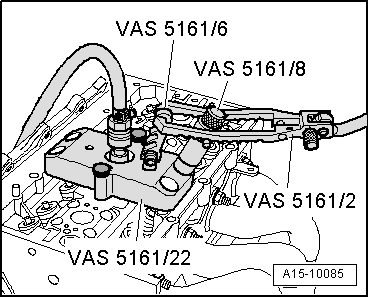
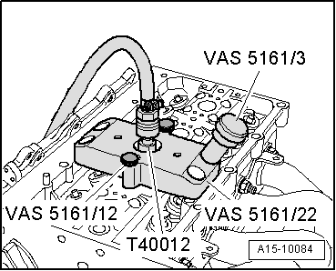
–  Screw snap-in device -VAS 5161/6- with engaging fork -VAS 5161/5- into guide plate -VAS 5161/22-.
–  Insert assembly cartridge -VAS 5161/8- into guide plate -VAS 5161/22-.
–  Attach pressure fork -VAS 5161/2- to snap-in device -VAS 5161/6- and push assembly cartridge -VAS 5161/8- down.
–  At the same time, turn knurled screw of assembly cartridge -VAS 5161/8- clockwise until ends engage in valve cotters.
–  Move knurled screw back and forth slightly; the valve cotters are thus forced apart and enter into cartridge.
–  Release the pressure fork.
–  Remove assembly cartridge -VAS 5161/8-.
–  Unbolt guide plate -VAS 5161/22- and move to side.
l  The compressed air hose remains connected.
–  Remove valve spring with valve spring plate.
  A15-10085
–  Remove valve stem oil seals using the valve stem seal puller -3364-.
  Note
  A15-0559
A plastic sleeve -A- is included with the new valve stem oil seals.
–  Insert plastic sleeve -A- onto the valve stem to prevent damage to the new valve stem oil seal -B-.
–  Lightly lubricate sealing lip of valve stem oil seal.
–  Slip valve stem oil seal over plastic sleeve.
–  Carefully press valve stem oil seal onto valve guide using valve stem seal fitting tool -3365-.
–  Remove the plastic sleeve.
  A15-0282
–  If valve cotters have been removed from assembly cartridge, they need to be put into insertion device -VAS 5161/18- first.
  Note
Larger diameter of valve cotters faces upwards.
  A15-0445
–  Insert valve spring and valve spring plate.
–  Screw guide plate -VAS 5161/22- back onto cylinder head.
–  Insert assembly cartridge -VAS 5161/8- into guide plate -VAS 5161/22-.
–  Push pressure fork down and pull knurled screw upwards while turning to left and right - this will insert the valve cotters.
–  Release the pressure fork with knurled screw still in pulled position.
–  Renew seals and O-rings for injectors → Rep. Gr.24.
–  Install fuel rail (bottom section of intake manifold) → Rep. Gr.24.
–  Install camshaft housing → Chapter.
–  Install camshaft timing chain → Chapter.
–  Install timing chain cover → Chapter.
–  Renew crankshaft oil seal → Chapter.
–  Install crankshaft pulley → Chapter.
–  Install intake manifold → Rep. Gr.24.
–  Install engine → Chapter.
  Note
After working on the valve gear, turn the engine carefully at least 2 rotations to ensure that none of the valves make contact when the starter is operated.
Tightening torque
  A15-10085
ComponentNm
Vacuum unit to fuel rail (bottom section of intake manifold)3
Engine lifting eye to cylinder head20


Checking valve guides > < Valves - exploded view of components