
A3 Mk2
| Checking valve timing |

| Special tools and workshop equipment required |
| t | Spark plug socket and extension -3122 B- |
| t | Torque wrench -V.A.G 1331- |
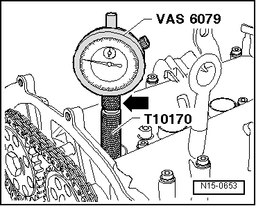
| t | Dial gauge -VAS 6079- |
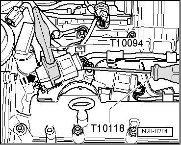
| t | Puller -T10094- |
| t | Adapter for dial gauge -T10170- |
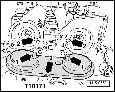
| t | Camshaft clamp -T10171- |
|
|
|
|
|
|
|
|
 Note
Note
|
|
|
|
Note
|
|
Note
|
|
| Component | Nm |
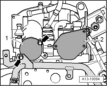
| Sealing caps to camshaft housing | 10 |