audi Workshop Repair Guides

Audi Workshop Service and Repair Manuals

Engine assy,cylinder block,crankcase > < Rules for cleanliness when working on the injection system
Important: Required procedure prior to opening high-pressure injection system
The injection system consists of a high-pressure section (maximum approx. 110 bar) and a low-pressure section (approx. 6 bar).
Prior to opening the high-pressure section (e.g. when removing the high-pressure pump, fuel rail (bottom section of intake manifold), injectors, intake manifold flap motor for air-flow control, a fuel line, or any other component located in the high-pressure zone of the injection system) the fuel pressure in the high-pressure section must be reduced to a residual pressure of approx. 8 bar. The procedure is described below.
–  Unplug electrical connector at solenoid valve 1 for activated charcoal filter system -N80-.
–  Start engine and run at idling speed.
   
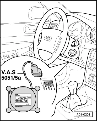
–  Connect vehicle diagnostic, testing and information system -VAS 5051- with diagnostic cable -VAS 5051/5 A-.
  A01-0201
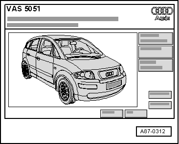
Display on -VAS 5051-:
–  Press the “Vehicle self-diagnosis” key.
  A87-0312
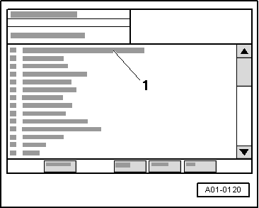
Display on -VAS 5051-:
–  From list -1- select vehicle system “01 Engine electronics”.
–  Wait until next display appears on tester.
  A01-0120
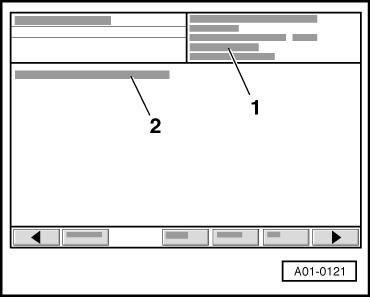
Display on -VAS 5051-:
1 - Engine control unit identification.
–  Press the key.
  A01-0121
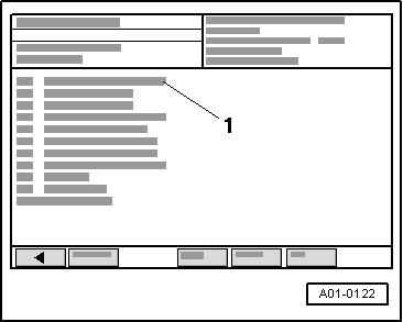
Display on -VAS 5051-:
1 - Selection of diagnostic functions
–  From the list -1- select diagnostic function “08 - Read measured value block”.
  A01-0122
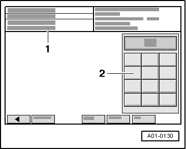
Display on -VAS 5051-:
–  In zone -2- enter “140” for “display group 140” and confirm the entry by pressing the Q key.
  A01-0130
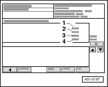
Display on -VAS 5051-:
–  Check fuel pressure in zone -3-:
l  With engine idling the figure displayed will be approx. 35 bar. The display shows the actual pressure in the fuel rail which is being generated by the high-pressure pump.
  Note
Display zone -2- shows the required pressure (specification). Actual pressure should match specification.
  A01-0187
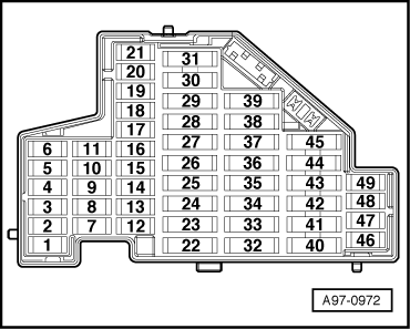
–  Remove fuse -27- for fuel pump control unit -J538- from fuse holder on dash panel (left-side).
  A97-0972
–  Leave engine running and observe fuel pressure displayed in zone -3- of -VAS 5051-.
l  The fuel pressure will decrease very quickly because the mechanical high-pressure pump is no longer being supplied with fuel from the fuel tank by the electric fuel pump.
–  Switch off ignition as soon as fuel pressure has dropped to approx. 8 bar.
  Note
Fuel pressure must not fall below 6 bar, otherwise the engine will stall (this could damage the catalytic converter).
The fuel rail (bottom section of intake manifold) is still filled with fuel, however it is no longer under high pressure.
Components or lines can now be opened. A clean cloth must be wrapped around the connections. Any discharged fuel must be collected.
–  Re-insert fuse for electric fuel pump control unit.
–  Interrogate and, if necessary, erase fault memory of engine control unit upon completion of repair work.
–  Generate readiness code in engine control unit in “Guided fault finding” mode.
  A01-0187

Engine assy,cylinder block,crankcase > < Rules for cleanliness when working on the injection system