| –
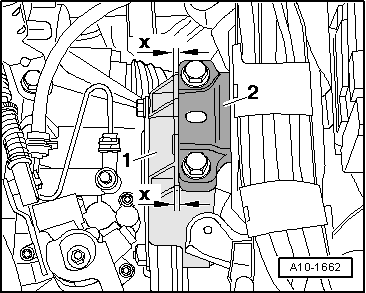
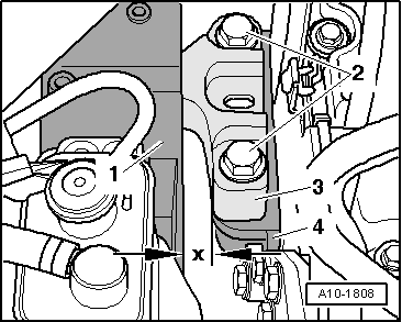
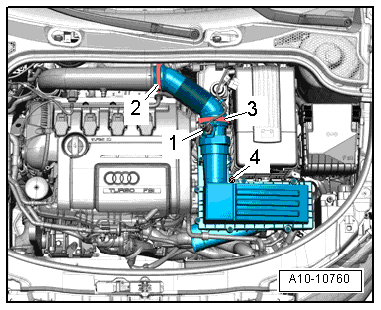
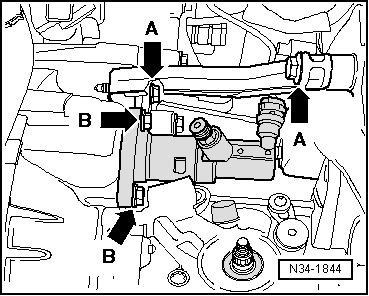
| Using a tyre iron, adjust engine/gearbox assembly between engine support -1- and support arm -3- of engine mounting until the specifications listed below are obtained: |
| l
| The two bolt heads -2- must be parallel with edge of support arm -3- for engine mounting. |
| l
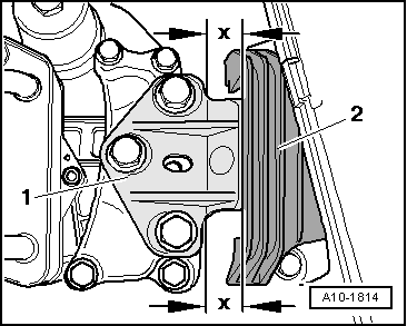
| There must be a distance of -x- = 16 mm between engine mounting -1- and engine support -4-. |

Note | Distance -x- = 16 mm can also be checked with a metal rod of suitable size, or similar. |
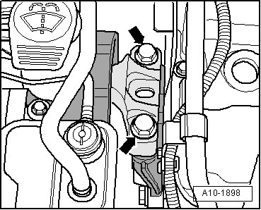
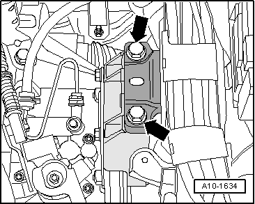
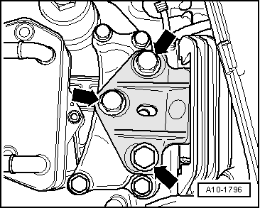
| –
| Tighten bolts securing engine mounting to engine support. |
|
|
|

 Caution
 WARNING