| –
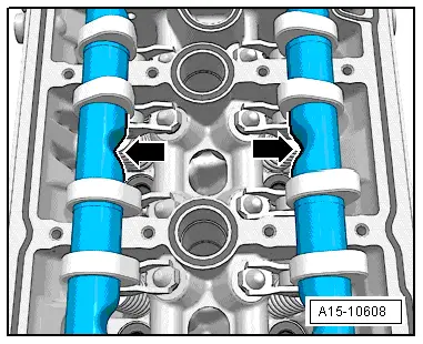
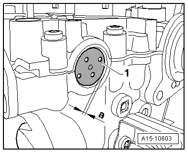
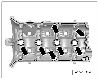
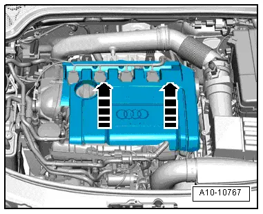
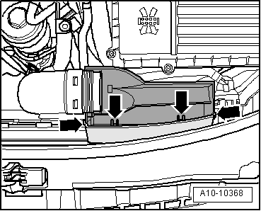
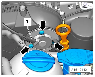
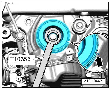
| Apply silicone sealant onto clean sealing surface of cylinder head cover, as illustrated -arrows-. |
| t
| Thickness of sealant bead: 2 ... 3 mm. |

Note | t
| The cylinder head cover must be installed within 5 minutes after applying the silicone sealant. |
| t
| The bead of sealant must not be thicker than specified, otherwise excess sealant can enter the sump and obstruct the strainer in the oil intake pipe. |
| t
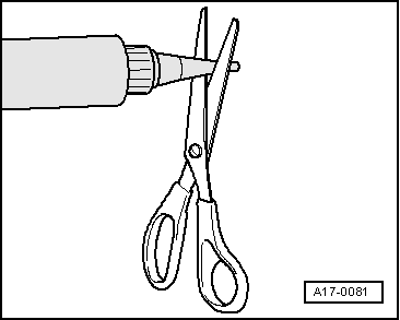
| Note the use-by date of the sealant. |
| –
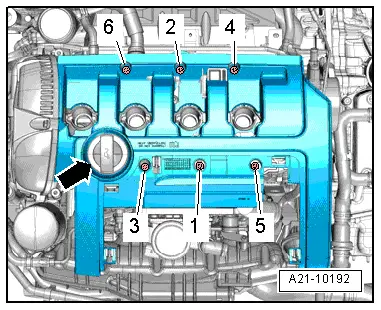
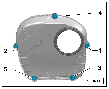
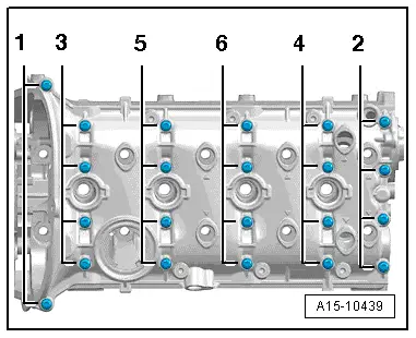
| Tighten bolts in several stages; tightening sequence → Fig.. |
Note | Take care to keep cylinder head cover straight. |
|
|
|

 Caution
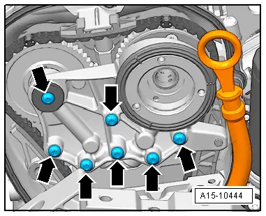
 WARNING