
A3 Mk2
| Pistons and conrods - exploded view |
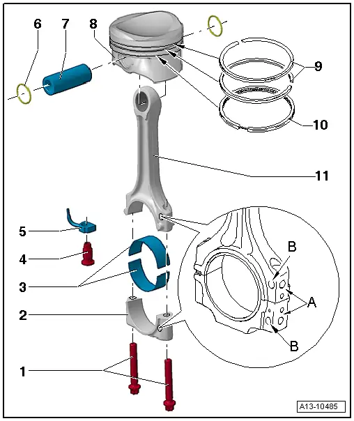
| 1 - | Conrod bolt |
| q | On vehicles with 1.8 ltr. engine: 30 Nm + turn 90° further |
| q | On vehicles with 2.0 ltr. engine: 45 Nm + turn 90° further |
| q | Renew |
| q | Lubricate threads and contact surface |
| q | Use old bolts when measuring radial clearance |
| q | To measure radial clearance, tighten to 30 Nm but do not turn further |
| 2 - | Conrod bearing cap |
| q | Note installation position |
| q | Due to the cracking method used to separate the bearing cap from the conrod in manufacture, the caps only fit in one position and only on the appropriate conrod |
| q | Mark cylinder allocation -A- |
| q | Installation position: Marking -B- faces towards pulley end |
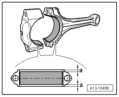
| 3 - | Bearing shells |
| q | Installation position → Fig. |
| q | Do not interchange used bearing shells (mark positions) |
| q | Axial clearance when new: 0.10...0.35 mm; wear limit: 0.40 mm |
| q | Check radial clearance with Plastigage - (new): 0.02 ... 0.06 mm; wear limit: 0.09 mm. Do not turn crankshaft when measuring radial clearance |
| 4 - | Pressure relief valve |
| 27 Nm |
| 5 - | Oil spray jet |
| q | For piston cooling |
| 6 - | Circlip |
| 7 - | Piston pin |
| q | If difficult to move, heat piston to approx. 60 °C |
| q | Remove and install using drift -VW 222 A- |
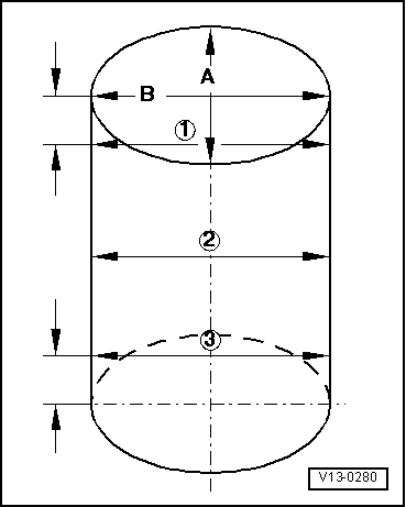
| 8 - | Piston |
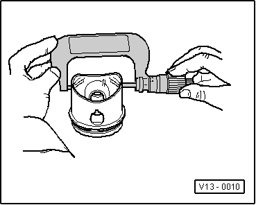
| q | Checking → Fig. |
| q | Mark installation position and cylinder number |
| q | Arrow on piston crown points to pulley end |
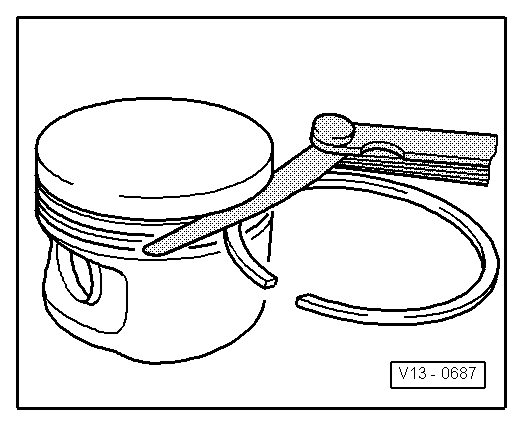
| q | Install using piston ring clamp |
| q | Piston and cylinder dimensions → Chapter |
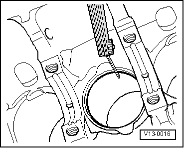
| q | Checking cylinder bore → Fig. |
| 9 - | Compression rings |
| q | Offset gaps by 120° |
| q | Use piston ring pliers to remove and install |
| q | “TOP” or “R” must face towards piston crown |
| q | Checking ring gap → Fig. |
| q | Checking ring-to-groove clearance → Fig. |
| 10 - | Oil scraper ring |
| q | 2 parts |
| q | Offset gap of top steel element of piston ring by 120° to next compression ring. |
| q | “TOP” or “R” must face towards piston crown |
| q | Offset gaps of individual parts of oil scraper ring. |
| q | Checking ring gap → Fig. |
| q | Ring-to-groove clearance cannot be checked. |
| 11 - | Conrod |
| q | Only renew as a complete set |
| q | Mark cylinder allocation -A- |
| q | Installation position: Marking -B- faces towards pulley end |
| q | Separating parts of new conrod → Chapter |
| Piston ring Dimensions in mm | New | Wear limit |
| Compression ring | 0.20...0.40 | 0.80 |
| Oil scraper ring | 0.25...0.50 | 0.80 |
|
|
| Piston ring Dimensions in mm | New | Wear limit |
| 1st compression ring | 0.06 … 0.09 | 0.20 |
| 2nd compression ring | 0.03 … 0.06 | 0.15 |
| Oil scraper rings | Cannot be measured | |
|
|
 Note
Note
|
|
 Caution
|
|