
A3 Mk2
| Renewing exhaust camshaft oil seal |
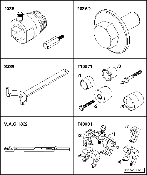
| Special tools and workshop equipment required |
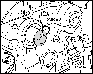
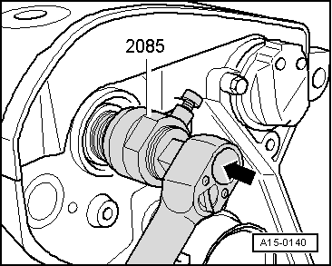
| t | Oil seal extractor -2085- |
| t | Adapter -2085/2- |
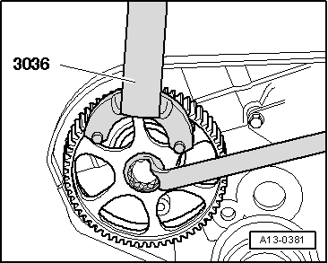
| t | Counterhold tool -3036- |
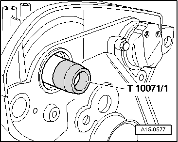
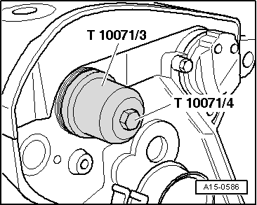
| t | Assembly tool -T10071- |
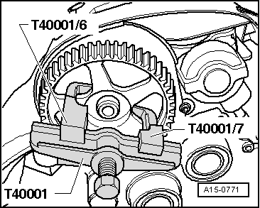
| t | Two-arm puller -T40001- with claw -T40001/6- and claw -T40001/7- |
| t | Torque wrench -V.A.G 1332- |
|
|
|
|
|
|
|
 WARNING
|
|
|
|
|
|
 Note
Note
|
|
|
|
|
|
Note
Note
|
|
|
|
|
|
|
|
Note
|
|
|
|
|
|
|
|
|
|
|
|
|
|
|
|
|
|
|
|
Note
|
|